Chapter 3 Connector and LED Information
X Series User Manual 3-2 ni.com
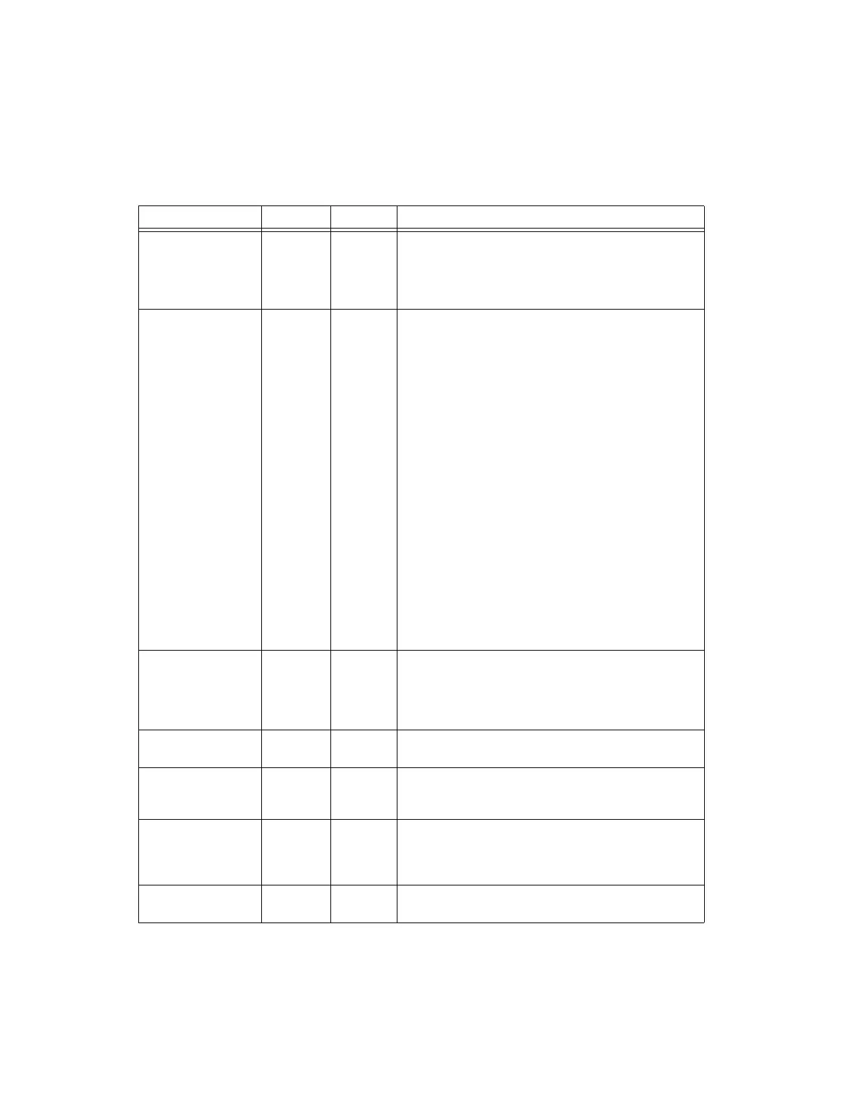
Table 3-1. I/O Connector Signals
Signal Name Reference Direction Description
AI GND — — Analog Input Ground—These terminals are the reference point
for single-ended AI measurements in RSE mode and the bias
current return point for DIFF measu rements. All three ground
references—AI GND, AO GND, and D GND—are connected on
the device.
*
AI <0..31> Var ies Input Analog Input Channels 0 to 31
(MIO X Series Devices) For single-ended measurements, each
signal is an analog input voltage channel. In RSE mode, AI GND
is the reference for these signals. In NRSE mode, the reference for
each AI <0..15> signal is AI SENSE; the reference for each
AI <16..31> signal is AI SENSE 2.
For differential measurements on MIO X Series devices, AI 0 and
AI 8 are the positive and negative inputs of differential analog
input channel 0. Similarly, the following signal pairs also form
differential input channels:
AI <1,9>, AI <2,10>, AI <3,11>, AI <4,12>, AI <5,13>,
AI <6,14>, AI <7,15>, AI <16,24>, AI <17,25>, AI <18,26>,
AI <19,27>, AI <20,28>, AI <21,29>, AI <22,30>, AI <23,31>
Also refer to the Connecting Ground-Referenced Signal Sources
section of Chapter 4, Analog Input.
(Simultaneous MIO X Series Devices) For differential
measurements on Simultaneous MIO X Series devices, AI 0+ and
AI 0– are the positive and negative inputs of differential analog
input channel 0.
Also refer to the Connecting Analog Input Signals section of
Chapter 4, Analog Input.
AI SENSE,
AI SENSE 2
— Input Analog Input Sense—In NRSE mode, the reference for each
AI <0..15> signal is AI SENSE; the reference for each
AI <16..31> signal is AI SENSE 2. Also refer to the Connecting
Ground-Referenced Signal Sources section of Chapter 4, Analog
Input.
AO <0..3> AO GND Output Analog Output Channels 0 to 3—These terminals supply the
voltage output of AO channels 0 to 3.
AO GND — — Analog Output Ground—AO GND is the reference for
AO <0..3>. All three ground references—AI GND, AO GND,
and D GND—are connected on the device.
*
D GND — — Digital Ground—D GND supplies the reference for P0.<0..31>,
PFI <0..15>/P1/P2, and +5 V. All three grou nd
references—AI GND, AO GND, and D GND—are connected on
the device.
*
P0.<0..31> D GND Input or
Output
Port 0 Digital I/O Channels 0 to 31—You can individually
configure each signal as an input or output.
Artisan Technology Group - Quality Instrumentation ... Guaranteed | (888) 88-SOURCE | www.artisantg.com

 Loading...


