3-10 | ni.com
Chapter 3 Hardware Overview
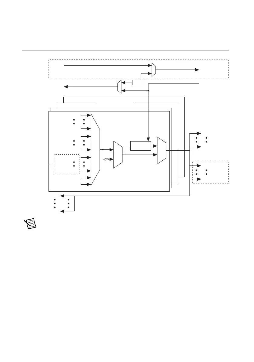
Figure 3-4 summarizes the routing features of the NI PXI-6683 Series. The remainder of this
chapter details the capabilities and constraints of the routing architecture.
Figure 3-4. High-Level Schematic of NI PXI-6683 Signal Routing Architecture
Note The NI PXI-6683H architecture is identical to the architecture described in
Figure 3-4, except that it doesn’t have the PXI_STAR trigger lines, CLKIN, or
PXI_CLK10_IN.
Determining Sources and Destinations
All signal routing operations can be characterized by a source (input) and a destination. In
addition, synchronous routing operations must also define a third signal known as the
synchronization clock. Refer to the Choosing the Type of Routing section for more information
on synchronous versus asynchronous routing.
Table 3-6 summarizes the sources and destinations of the NI PXI-6683 Series. The destinations
are listed in the horizontal heading row, and the sources are listed in the column at the far left.
A
in a cell indicates that the source and destination combination defined by that cell is a valid
routing combination.
PXI_Trig 0
PXI_Trig 7
PXI_Star 0
PXI_Star 12
Router for each I/O
PFI 0
PFI 2
PXI_Trig 0
PXI_Trig 7
PXI_Star 0
PXI_Star 12
GND
Clk10
Synchronizer
TCXO
ClkIn
ClkOut
PXI_Clk10_In
PXI_Clk10
PFI 0
PFI 2
PXI_Clk10
Not in NI PXI-6683H
Not in NI PXI-6683H
Not in
NI PXI-6683H

 Loading...