3-18 | ni.com
Chapter 3 Hardware Overview
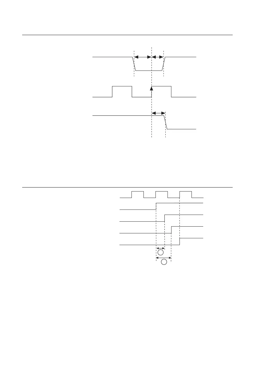
Figure 3-7. Synchronous Routing Operation
Synchronous routing can be useful for eliminating skew when sending triggers to several
destinations. For example, when sending triggers using the PXI Trigger lines, the trigger arrives
at each slot at a slightly different time. However, if the trigger is sent and received synchronously
using a low-skew synchronization clock, such as PXI_CLK10, all receiving devices can act on
the trigger at the same time, as shown in Figure 3-8.
Figure 3-8. Synchronous Routing to Multiple Destinations
Synchronous routing requires the input to be stable at a logic low or logic high state within a
window of time around the clock edge. This window of time around the clock edge is defined
by the setup time (tsetup) and hold time (thold). If the input signal changes within this window
of time, it is undetermined whether the output of the synchronous route will go to the old or new
logic state. This is important, for example, if a source is being routed synchronously to several
destinations. As shown in Figure 3-9, if the source signal changes within the setup-and-hold
Trigger Input
Synchronization
Clock
Trigger Output
Setup
Time
t
setup
Hold
Time
t
hold
Clock to Output
Time, t
CtoQ
PXI_CLK10
Trigger@Destination 2
Trigger@Destination 1
Trigger Out@Source
Trigger Synchronously Received
@Destinations 1 and 2
A
B
A: Propagation delay from source to destination 1.
B: Propagation delay from source to destination 2.

 Loading...