© National Instruments | 3-19
NI PXI-6683 Series User Manual
window around the synchronization clock edge, one of the destinations might go to the new logic
level while the other destination might remain at the old logic level and change when the next
synchronization clock edge occurs.
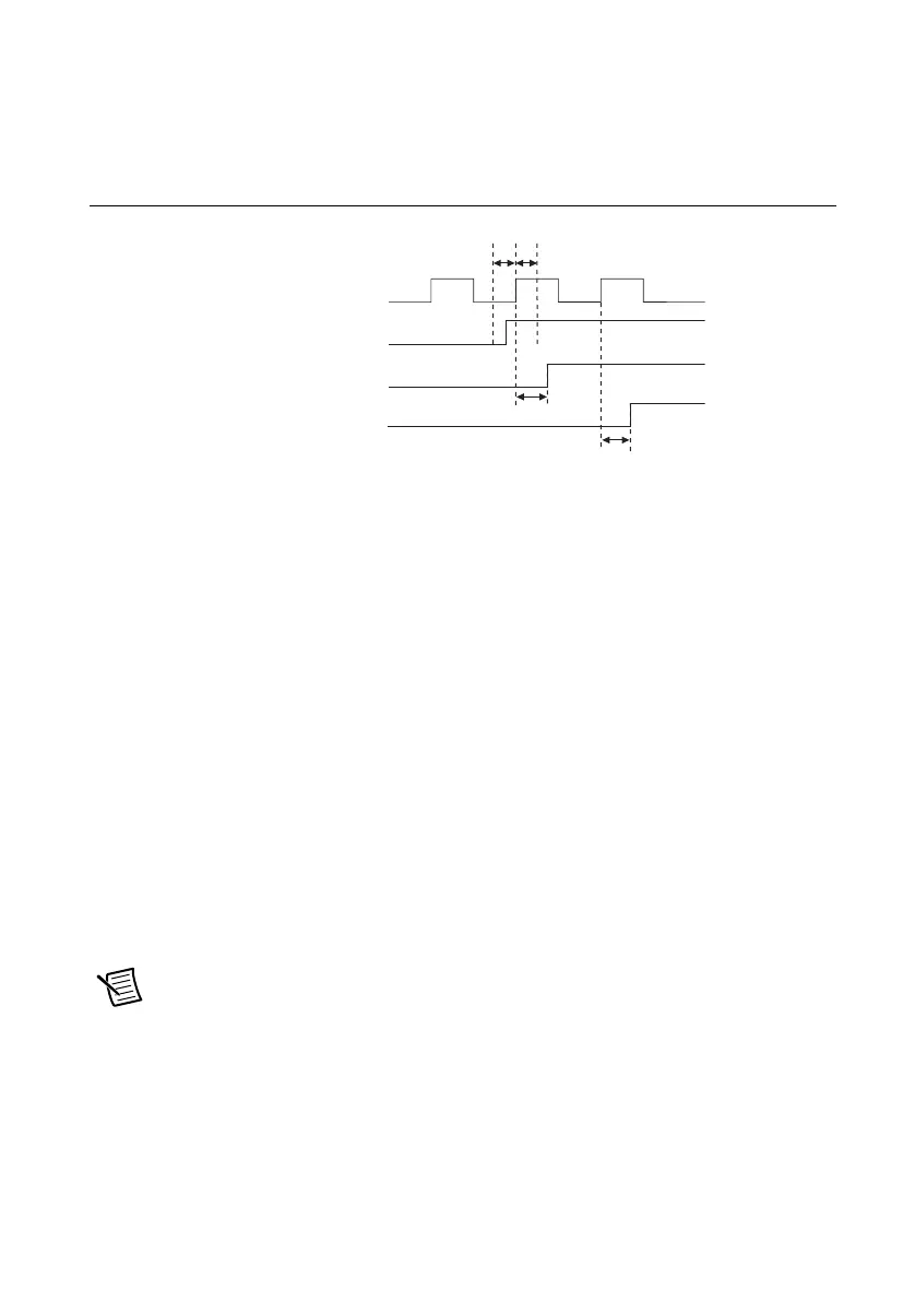
Figure 3-9. Synchronous Routing Uncertainty with Setup-and-Hold Violation
Therefore, if your application requires that the trigger arrive at the multiple destinations
simultaneously, you must ensure that the input is stable within the setup and hold window around
the synchronization clock edge. For more information and possible methods to ensure this
requirement is met, go to
ni.com/info and enter Info Code SyncTriggerRouting.
Possible sources and destinations for synchronous routing include the following:
• Any front panel PFI pin (PFI<0..2>)
• Any PXI star trigger line (PXI_STAR<0..12>) (NI PXI-6683 only)
• Any PXI Trigger line (PXI_TRIG<0..7>)
In the NI PXI-6683 Series, the synchronization clock for synchronous routes is always
PXI_CLK10.
The destination of a synchronous routing operation on the NI PXI-6683 Series can be any of the
following lines:
• Any front panel PFI pin (PFI<0..2>)
• Any PXI star trigger line (PXI_STAR<0..12>) (NI PXI-6683 only)
• Any PXI Trigger line (PXI_TRIG<0..7>)
Note The possible destinations for a synchronous route are identical to those for an
asynchronous route.
Synchronization CLK
Trigger Output 2
Trigger Ouput 1
Trigger Input
t
setup
t
hold
t
CtoQ
t
CtoQ

 Loading...