© National Instruments | B-3
NI PXI-6683 Series User Manual
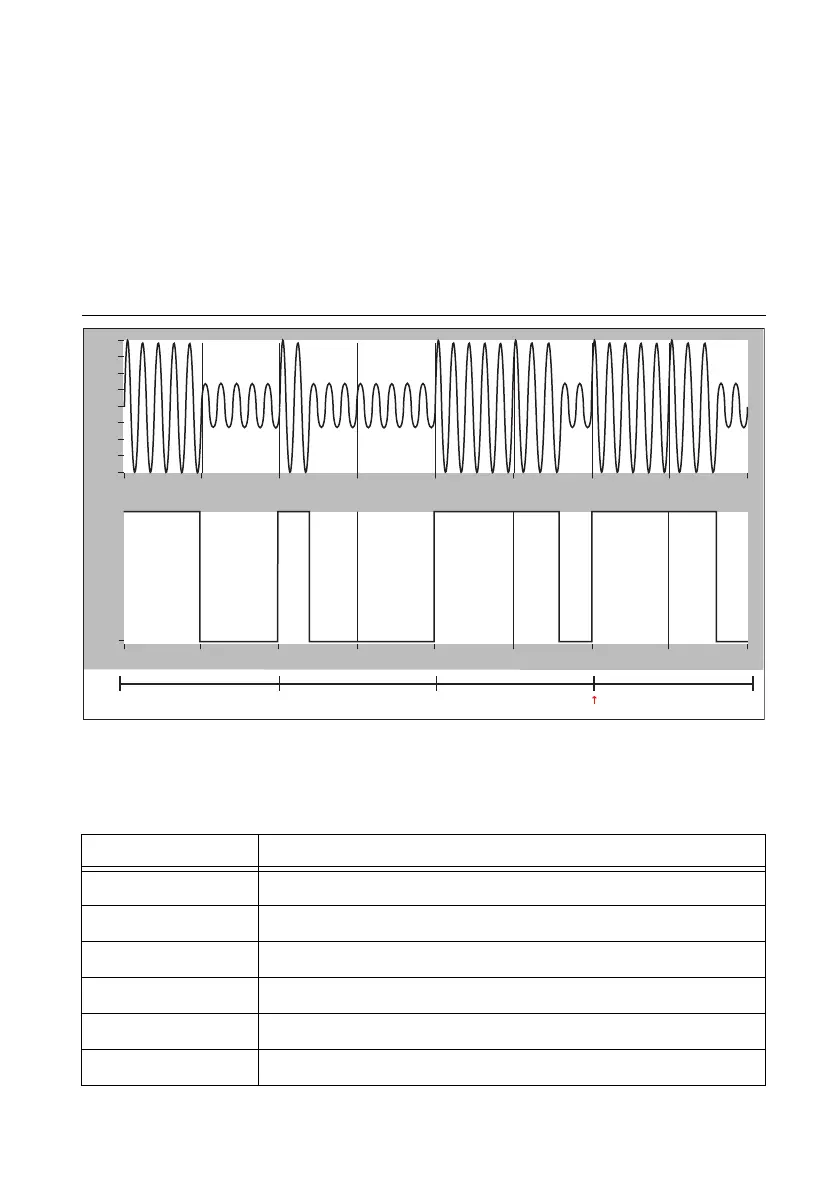
For amplitude modulated systems, the source must generate sinusoidal signaling modulating the
amplitude such that it has a 10:3 mark:space amplitude ratio (the range of allowable mark to
space ratios is 3:1 to 6:1). The source must phase align the generated sine wave such that the
leading edges of bits are coincident with zero crossings of the sine wave.
Figure B-1 shows an example of transmission of a binary one, a binary zero, and two position
identifiers (with the second’s boundary at the leading edge of the second position identifier). The
figure shows the information transmitted using an amplitude modulated signal, and a pulse width
modulated signal.
Figure B-1. IRIG-B AM and DC Transmission Example
IRIG-B is one of the most common IRIG standards used. The following table describes how the
information is transmitted when using IRIG-B each second.
Table B-3. IRIG-B Bit Assignments
Bit position Information transmitted
0 Position identifier P
R
(seconds’ boundary marker)
1 to 4 Units of seconds
6 to 8 Tens of seconds
9 Position identifier P
1
10 to 13 Units of minutes
15 to 17 Tens of minutes
Binary One Binary Zero Position Identifier Position Identifier
Second’s Boundary
Logic Level Amplitude
–4
–3
–2
–1
0
1
2
3
4
0
1
=
0 5m 10m 15m 20m 25m 30m 35m 40m
Time
0
5m 10m 15m 20m 25m 30m 35m 40m
Time

 Loading...