22 | ni.com | NI 5114 Calibration Procedure
13. Connect the calibrator test head directly to the channel 0 input of the device and output the
Negative Offset voltage listed in Table 7 for the current iteration with a 1 MΩ load
impedance.
14. Wait 2,500 ms for the impedance matching and frequency of the calibrator to settle.
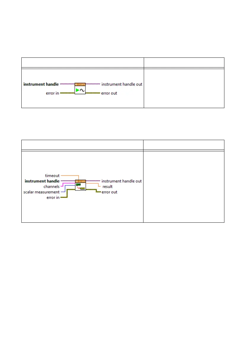
15. Initiate a waveform acquisition using the niScope Initiate Acquisition VI.
16. Fetch a waveform from the device and perform a voltage average measurement using the
niScope Fetch Measurement (poly) VI. Select the Measurement Scalar DBL instance of the
VI. This value is the Measured Negative Voltage used in step 17.
17. Calculate the error in the programmable vertical offset as a percentage of input using the
following formula:
where
a is the Measured Positive Voltage
b is the Measured Negative Voltage
c is the applied Positive Voltage
d is the applied Negative Voltage
LabVIEW VI C/C++ Function Call
Call
niScope_InitiateAcquisit
ion
with the following parameter:
vi: The instrument handle from
niScope_init
LabVIEW VI C/C++ Function Call
Call
niScope_FetchMeasurement
with the following parameters:
timeout: 1.0
vi: The instrument handle from
niScope_init
channelList: "0"
scalarMeasFunction:
NISCOPE_VAL_VOLTAGE
_AVERAGE
error
ab–
cd–
----------- -
1–
100×=
 Loading...


