Using the SCB-68 with Multifunction I/O Devices
You can take measurements with the SCB-68 and multifunction I/O (MIO) DAQ
products, such as NI 60xx/61xx/62xx/63xx, in a number of ways. Switches S1 and S2
provide power to the signal conditioning area of the accessory. The SCB-68 has a
temperature sensor for cold-junction compensation (CJC) to accommodate
thermocouples; switches S3, S4, and S5 configure the temperature sensor for
dierent analog input settings. The following table shows the dierent switch
settings for MIO DAQ devices.
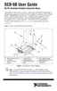
Switch Setting Description
MIO with disabled temperature sensor mode (default configuration)
*
—Move
switches S1, S2, S3, S4, and S5 to the positions shown at le. In this mode:
■
The temperature sensor is not used.
■
AI 0 and AI 8 are available on screw terminals.
■
+5 V power provided to signal conditioning area of the accessory.
Refer to the following figure for a detailed diagram.
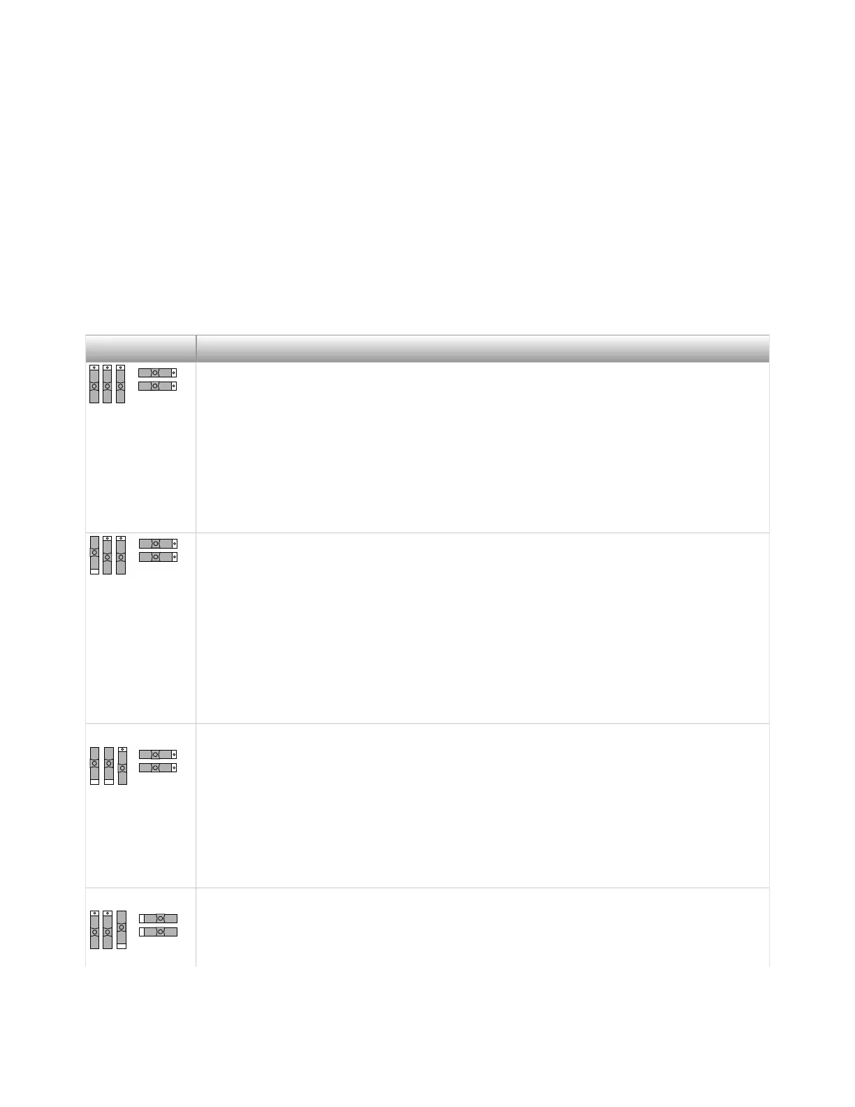
MIO with single-ended temperature sensor mode
*,†
—Move switches S1, S2, S3,
S4, and S5 to the positions shown at le. In this mode:
■
The temperature sensor can be read using AI 0 in referenced single-
ended (RSE) mode.
■
AI 8 is available on a screw terminal.
■
+5 V power provided to signal conditioning area of the accessory.
Refer to the following figure for a detailed diagram.
MIO with differential temperature sensor mode—Move switches S1, S2, S3, S4,
and S5 to the positions shown at le. In this mode:
■
The temperature sensor can be read using AI 0 and AI 8 in dierential
mode.
■
+5 V power provided to signal conditioning area of the accessory.
Refer to the following figure for a detailed diagram.
Direct feedthrough mode—Move switches S1, S2, S3, S4, and S5 to the positions
shown at le. In this mode:
■
All 68 signals from the device connect directly to screw terminals.
ni.com
8
SCB-68 Getting Started

 Loading...