Switch Setting Description
Refer to Using the SCB-68 in Direct Feedthrough Mode for a detailed diagram.
* Not available on Connectors 1, 2, 3 of NI 6225/6255 or NI 6345/6355/6365/6375 devices.
† Not available on NI 61xx devices.
Table 2. MIO DAQ Device Switch Settings
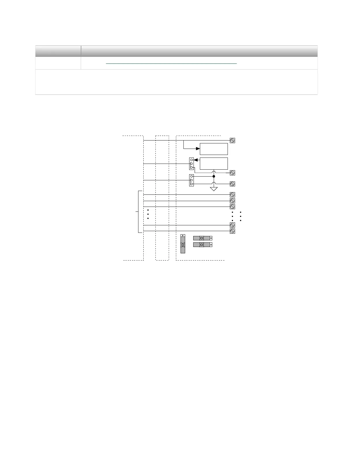
Figure 4. MIO Device Modes Switch Settings
Temperature
Sensor
MIO DAQ Device Cable SCB-68
S5
S4
Screw
Terminal
67
66
3
2
1
34
8
68
67
66
3
2
1
34
8
68
S3
S1
S2
+5 V
AI 0
AI 8
Other
Pins
Refer to
Your Device
Documentation
for Device
Signal
Information
Signal
Conditioning
Connecting Signal Sources to Analog Inputs
For detailed information about connections from floating or ground-referenced
signal sources to analog inputs, refer to your device documentation.
Refer to the SCB-68 User Manual for Advanced Functions for more information
about using the temperature sensor, taking thermocouple measurements, and
adding bias resistors and signal conditioning components to the SCB-68.
Fuse and Power Information
Some DAQ devices provide +5 V power on pin 8 and pin 14. Pin 8 from the DAQ
device is protected by an 800 mA, 250 V, 5 × 20 mm fuse on the SCB-68, shown in
Figure 2. Shorting pin 8 to ground blows the fuse on the SCB-68. Pin 14 is not fuse-
© National Instruments
9
SCB-68 Getting Started
 Loading...