Chapter 3 Signal Connections
© National Instruments Corporation 3-5 SCXI-1120/D User Manual
Analog Input Channels
The SCXI-1120/D positive input channels are located in Figure 3-1
column A. Their corresponding negative input channels are located in
column C. Each input corresponds to a separate amplifier and is fully
isolated from the other channels and from earth ground. The inputs are
designed in a floating single-ended configuration, thus the measured signal
can be referenced to a ground level with common-mode voltage up to
250 V
rms
. For better noise immunity, connect the negative input channel
to the signal reference. If the measured signals are floating, connect
the negative input channel to chassis ground on the terminal block.
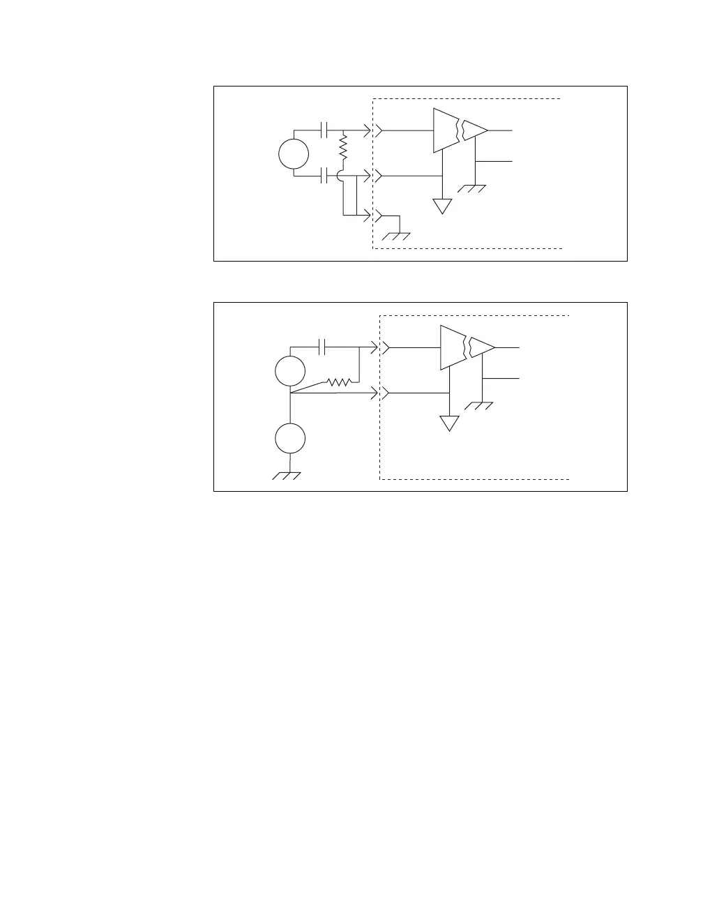
Figure 3-2 shows how to connect a ground-referenced signal on the
SCXI-1120/D. Figure 3-3 shows how to connect a floating signal on the
SCXI-1120/D. Figures 3-4 through 3-7 show how to connect AC-coupled
signals on the SCXI-1120/D.
Figure 3-2.
Ground-Referenced Signal Connection for the SCXI-1120/D
with High Common-Mode Voltage
Figure 3-3.
Floating Signal Connection for the SCXI-1120/D Referenced to
Chassis Ground for Better Signal-to-Noise Ratio
Module
+
-
+
+
+
-
-
I
out
V
s
V
cm
V
High
CMV
Module
+
-
+
+
-
I
out
V
s
V
 Loading...