Chapter 3 Signal Connections
SCXI-1120/D User Manual 3-6 www.natinst.com
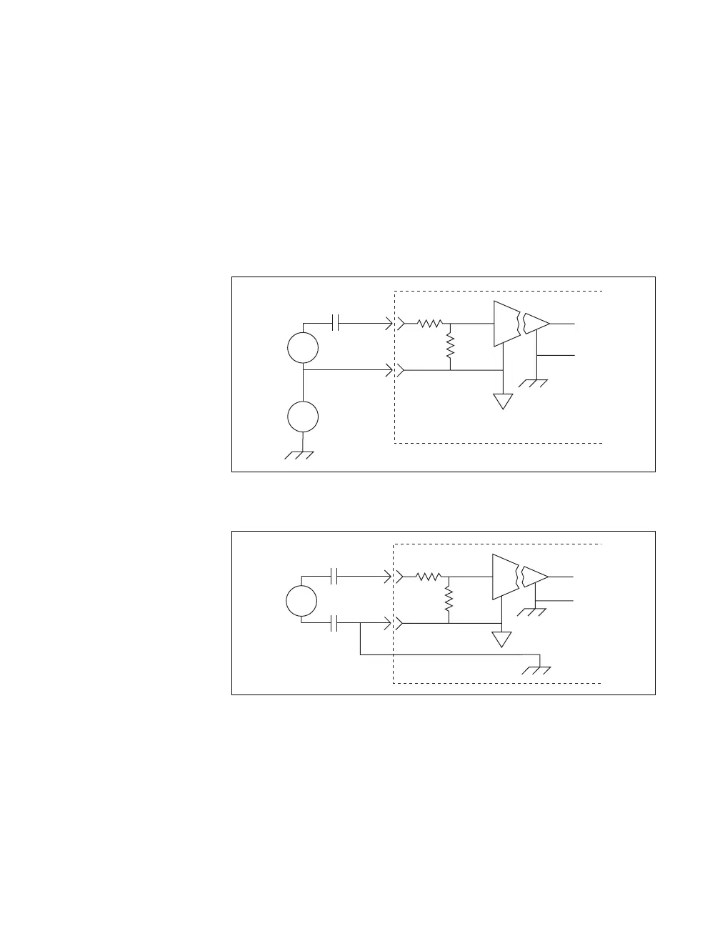
Figure 3-4. Floating AC-Coupled Signal Connection for the SCXI-1120
Figure 3-5. AC-Coupled Signal Connection for the SCXI-1120 with
High Common-Mode Voltage
♦ SCXI-1120
When you connect AC-coupled signals to the SCXI-1120, connect an
external resistor from the positive input channel to the signal reference to
provide the DC path for the positive input bias current. Typical resistor
values range from 100 kΩ to 1 MΩ. This solution, although necessary in
this case, lowers the input impedance of the input channel amplifier and
introduces an additional offset voltage proportional to the input bias current
and to the resistor value used. The typical input bias current of the amplifier
consists of ±80 pA and a negligible offset drift current. When a 100 kΩ
resistor is used, this will result into ±8 µV of offset, which is insignificant
in most applications. However, if larger valued bias resistors are used,
significant input offset may result. To determine the maximum offset
introduced by the biasing resistor, use the following equation:
Module
+
-
+
+
-
I
V
out
V
s
Module
+
-
+
+
-
I
out
V
s
V
+
-
cm
V
R
bias
High
CMV
V
ofsbias
I
bias
R
bias
×=
 Loading...