NV30/NV40 Operations and Maintenance Manual Operating the transmitter
Page 2-30 Issue 3.3 2014-12-10
Available instrument panels
Spectrum Analyser
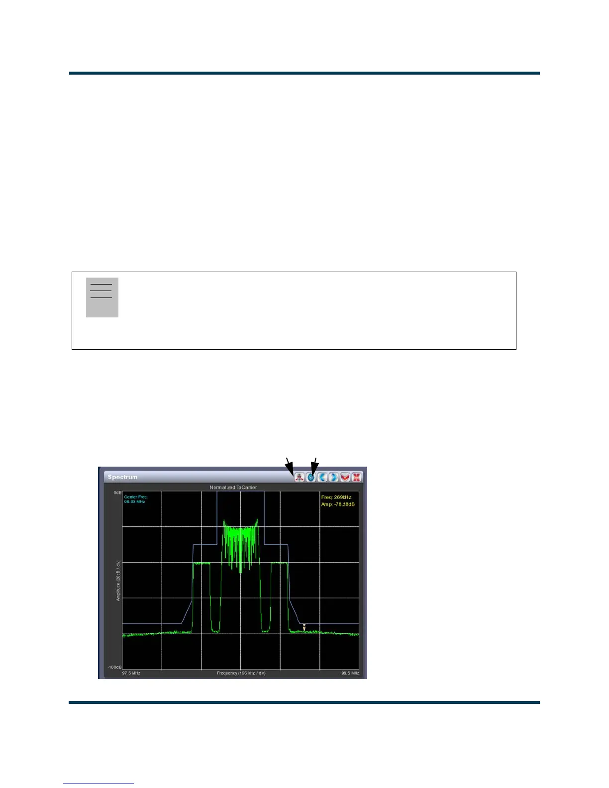
See Figure 2.20. The carrier level is normalized to its unmodulated carrier level at 0 dB. The graph
center is always at the carrier frequency, as defined by the active preset’s Frequency value
.
Masks are shown based on transmission mode and are defined by the latest versions of the following
standards:
•IBOC: NRSC-5
• European Standard: ETSI EN 302 018-2
• FCC CFR 47, Part 73.317 and IC BETS-6e
Touch on the panel to display a cursor in the approximate area. The cursor position (frequency and
amplitude) is noted in the upper, right-hand corner of the panel. Touch other areas of this instrument
panel to provide a coarse adjustment of the cursor position.
Figure 2.20: Spectrum Analyzer
Note:
While very accurate, the spectrum analyzer may display artifacts (spurs) as some operating carrier
frequencies that are a function of the analyzer and are not actually present on the output of the
transmitter. If these spurious emissions are observed on the spectrum analyzer, Nautel
recommends that a calibrated, external spectrum analyzer be used to verify the presence of spurs.
 Loading...


