NV30/NV40 Operations and Maintenance Manual Operating the transmitter
Page 2-68 Issue 3.3 2014-12-10
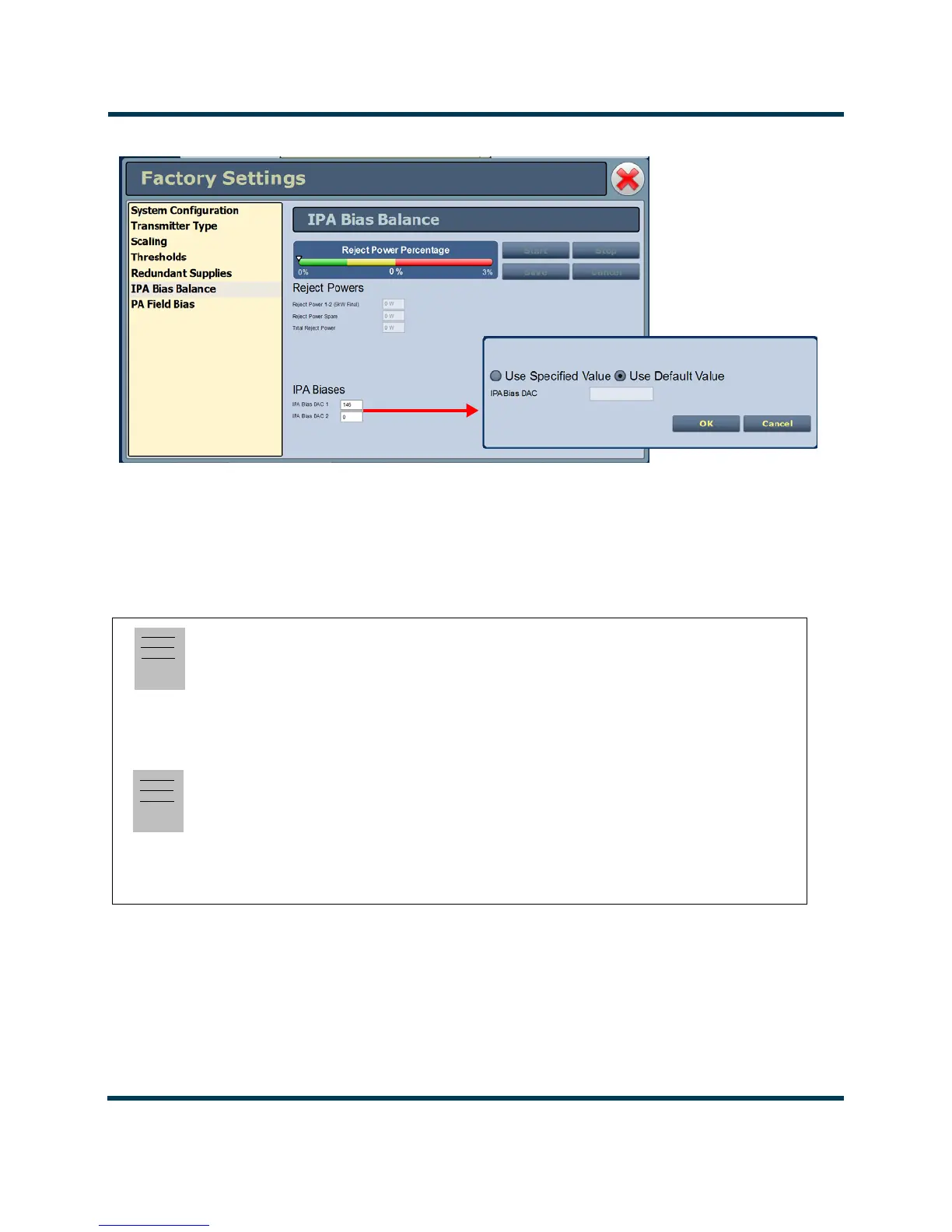
Figure 2.49: Factory Settings - IPA Bias Balance
Note:
The IPA Bias Balance function targets the lowest possible total transmitter reject power. However,
there is no guarantee that it will achieve less than a specific amount. Variables such as RF module
output power and phase differences result in system reject power that can sometimes not be
compensated for with this function.
Note:
The Reject Power Percentage meter is only available in this functional menu. The green/amber/
red colours are simply to provide user feedback as to the progress of the function. If the transmitter
is operating normally, without fault, and the total reject power percentage falls within the amber
or red "post" an IPA bias balance routine, there is nothing to be concerned with, the function is
simply not able to completely compensate for the reject power (phase/amplitude differences).
IPA Bias DAC 1 = Module 1
IPA Bias DAC 2 = Module 2
 Loading...


