NV5/NV3.5 Troubleshooting Manual Responding to alarms
Page 1-26 Issue 3.2 2014-12-10
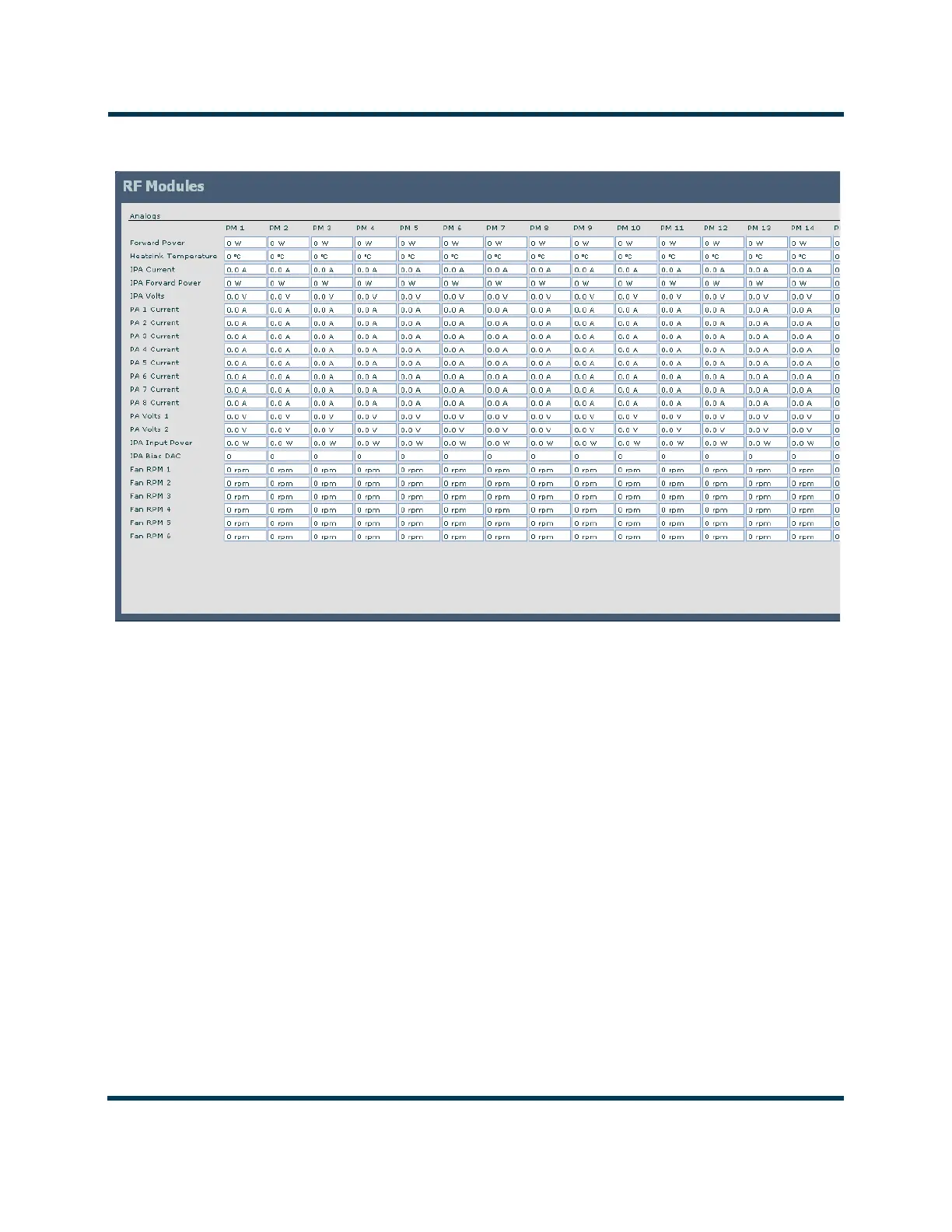
Figure 1.2: Module Status Screen
RF power module fault validation
Each RF power module has a multi-colour LED on its front panel, which can help in identifying a
fault and allowing you to determine whether remedial action is required now or later.
Identify and isolate a defective RF power module, and verify the nature of the defect by checking the
LED on the RF power module’s front panel. Note which RF power module is not operating normally
and producing RF power (i.e., LED is not solid green). Record which RF power modules are
displaying an alarm and the state of its LED (see below).
For all Module alarms, the Description and Troubleshooting Action column of Table 1.1 on
page 1-7 includes the expected LED colour for the AUI alarm being described.
– Green: Module is operational
– Green/Red: Module is operational, but has a non-inhibiting fault.
– Amber: Module is inhibited, but in a ready state (i.e., RF off).
– Red: Module is inhibited by a fault, or serially.
– Red/Amber: Module is not communicating with the AUI/Controller.