Transmission ON Transmission OFF
ALARM OUT:
If you want to signal an alarm with a LED only, you can connect the LED with a series resistor R
between + (grey) and ALARM OUT (yellow). Depending on the Voltage used for the Nauticast B2
you either have to use a 470(calculated 500) resistor (LED: U
F
=2V, I
F
=20mA) when using
12VDC or a 1k (calculated 1100 when using 24VDC.
See calculation in the Section for CABLE 4.
How to connect a LED to Alarm OUT
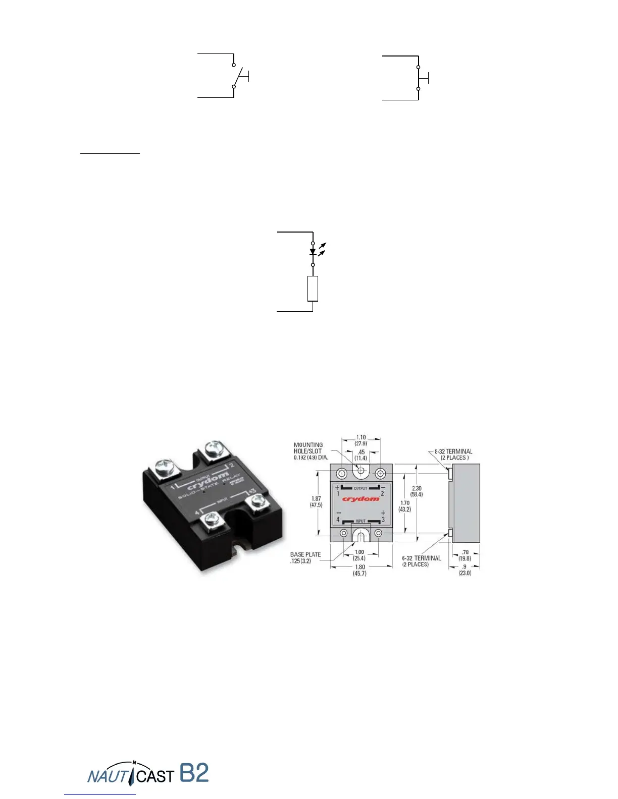
The next figures show the alarm relay (prod. no.: 3001009) and its dimensions, explain how to
connect the alarm relay to the data cable and how to connect the load (alarm circuit) to the alarm
relay. The input voltage of the alarm relay is matched with the operating voltage of the Nauticast
B2. The operating voltage of the alarm relay is 3 to 60 VDC with a load current of 0.1 to 2 A (3A
when using a heat sink).
Alarm Relay with dimensions


 To Next Page