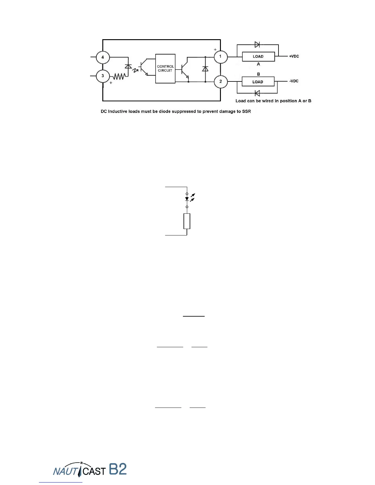
Connection of the Alarm Relay
CABLE 4:
Depending on the Voltage used for the Nauticast B2 you have to calculate the series resistor which
is connected with the LED between the + wire (grey) and the OUTPUT wire (CH1 LED RED, green;
CH2 LED RED, brown; TX TIMEOUT LED, white; ERROR LED, yellow). A series resistor of 330
(calculated 350) for 12VDC and 910 or 1k (calculated 950) for 24VDC are needed - see
calculation below.
How to connect a LED to XXX LED OUT
Calculation of the series resistor: Used variables
U... operating voltage of the Nauticast B2
U
F
... Forward Voltage of LED [V]
I
F
... Forward Current of LED[V]
R... Series Resistor[Ω]
P... Power consumption of the resistor[W]
Examples:
U=12V, U
F
=2V, I
F
=20mA:
As there is already a 150 resistor included for the LED OUT ports, you have to substract this from
the 500. Therefore 350 is the result.
(!) The ALARM OUT has no resistor included therefore 500 is the result. (see CABLE 3)
U=24V, U
F
=2V, I
F
=20mA:
As there is already a 150 resistor included for the LED OUT ports, you have to substract this from
the 1100. Therefore 950 is the result. (!) ALARM OUT has no resistor included, therefore the
result is 1100 (see CABLE 3).