13
Nautilus® Commercial Free Weights Adjustable Tower Assembly Manual
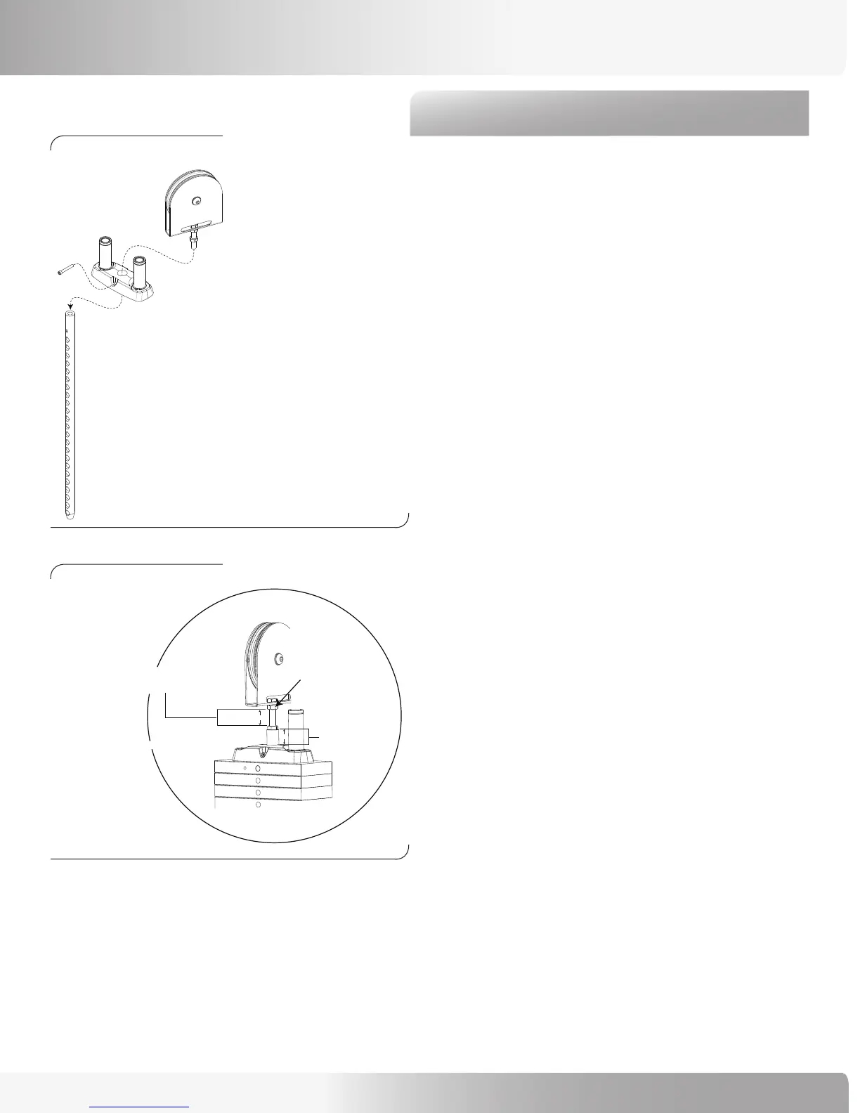
Step 3: Assemble Stack Pulley and Top Weight Plate
Locate the following for this step:
Parts:
• Ref 10, Stack Pulley Assembly Qty. 1
• Ref 3, Top Weight Plate Assembly Qty. 1
• Ref 11, Stem Pin Qty. 1
Hardware:
• Ref 12, 1/4” x 1 3/4” Socket Head Cap Screw Qty. 1
Tools:
• Ref 14, 3/16” Allen Wrench
Refer to Figures 3 and 4:
3-1 Prepare the Top Weight Assembly by loosely
attaching the Stack Pulley Assembly.
3-2 Attach the Stem Pin.
3-2 Set aside the Assembly.
Note: When attaching the Weight Stack Pulley, make
sure that there is 25.4 mm (1in.) of thread engagement
(Figure 4). In order to ensure proper thread engagement,
set the bottom nut at the 25.4 mm (1in.) minimum
distance, then thread the Pulley Assembly into the Top
Weight (refer to Step 12 for the procedure to thread the
Pulley Assembly). To check that you have the proper
engagement after the Pulley is installed, measure the
distance between the two nuts when the top nut is fully
tightened. The distance between nuts can not exceed
22.4 (.88 in.) mm.
Figure 3:
Figure 4:
ASSEMBLY GUIDE
GAP MUST BE FROM 0.0MM TO 22.4MM
DURING NORMAL OPERATION TO ALLOW
MINIMUM THREAD ENGAGEMENT.
TOP NUT MUST BE FULLY
TIGHTENED BEFORE
MEASURING GAP
25.4 MINIMUM
THREAD ENGAGEMENT
22.4
25.4
IF GAP EXCEEDS 22.4 MM, REPLACE THE CABLE.