Do you have a question about the Nautilus F3AT and is the answer not in the manual?
General safety instructions and definitions for warnings used in the manual.
Specific caution regarding the machine's orientation when the weight stack is attached.
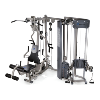
Technical details including user weight capacity, dimensions, and shipping weight.
Provides fundamental tips to ensure a quick and easy assembly process.
Guidance on safely moving and positioning the heavy equipment before assembly.
Illustrates and lists all hardware components with reference numbers for assembly.
Lists the essential tools that users must supply for the assembly process.
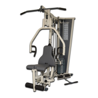
Instructions for assembling the main frame triangle and rear upright components.
Instructions for attaching the left and right upright frame sections to the assembly.
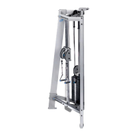
Guidance on assembling the weight stack pulley mechanism and the top weight plate.
Instructions for installing the guide rods and bumpers for the weight stack mechanism.
Procedures for correctly placing the individual weight plates onto the guide rods.
Instructions for placing specific components onto the ends of the guide rods.
Steps to secure the guide rods into the upper triangle section of the frame.
Instructions for preparing and applying decals to the weight plates for identification.
Guidance on assembling the components of the adjustable pulley system.
Instructions for attaching the assembled adjustable pulley system to the main frame.
Procedures for securing the lower pulley assemblies to the machine frame.
Instructions for attaching the upper pulley assemblies to the top of the frame.
Detailed steps for routing the main cable through the various pulley systems.
Continuation of cable routing instructions, covering additional pulley paths.
Final procedures for lubricating moving parts and adjusting cable tension.
Final visual inspection and testing of the assembled equipment before use.
| Bluetooth | Yes |
|---|---|
| Cooling Fan | Yes |
| Speakers | Yes |
| Motor | 3.0 HP |
| Running Area | 20" x 60" (50.8 x 152.4 cm) |
| Incline | 15% |
| Speed | 0 – 12 mph (0 – 19.3 km/h) |