19
Nautilus® Commercial Free Weights Adjustable Tower Assembly Manual
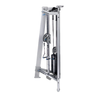
Step 9: Assemble Adjustable Pulley System
Locate the following for this step:
Parts:
• Ref 4, Tube, Adjustment Qty. 1
• Ref 7, Spacer, Adjustment Tube Qty. 4
• Ref 7, Bracket, Lower Adjustment Tube Qty. 1
• Ref 9, Dual Adjustable Pulley System Qty. 1
Hardware:
• Ref 5, 1/2”x 3” Button Head Bolt Qty. 2
• Ref 4, 1/2”x 2 3/4” Button Head Bolt Qty. 1
• Ref 10, 1/2” Locknuts Qty. 3
• Ref 9, 1/2” Washers Qty. 6
Tools:
• Ref 16, 5/16” Allen Wrench
• 3/4” Wrench
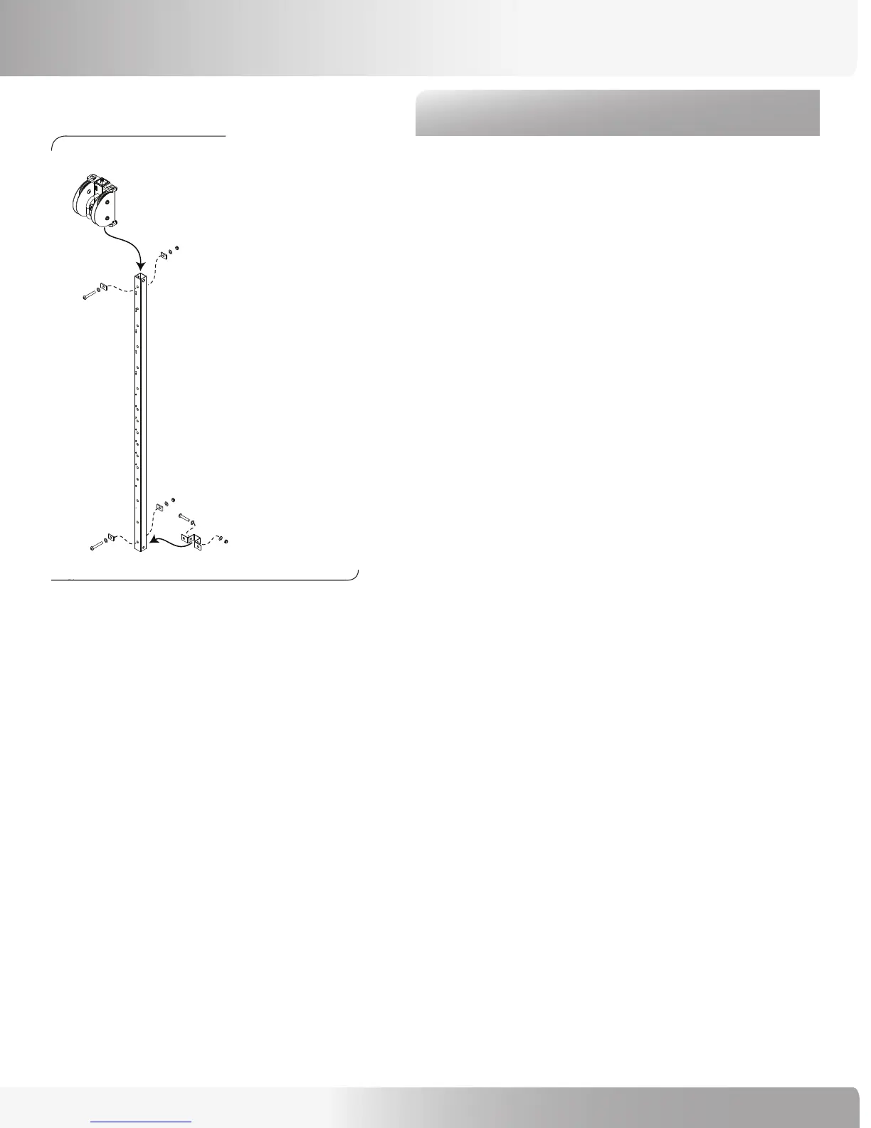
Refer to Figure 11:
9-1 Position the Adjustment Tube so that the numbers
on it face you.
9-2 Place a spacer on the front and back of
the bottom most holes and secure with a 3” bolt.
Firmly tighten the hardware.
9-3 Place the Bracket, Lower Adjustment Tube over
the bottom-most holes on the side of the
Adjustment Tube and secure with a 2 3/4” bolt
(but leave the hardware loose).
9-4 Slide the Dual Adjustment Pulley System
Assembly over the top of the Adjustment Tube
and lock into the #1 location. Note: the Dual
Adjustment Pulley System can be positioned
upside down; upright is when the viewer
window is at the top.
9-5 With the Adjustment Tube numbers facing you,
place a spacer on the front and back of the
top-most holes and secure with a 3” bolt.
Firmly tighten the hardware (except the bottom
bracket bolt).
Figure 11:
ASSEMBLY GUIDE