57
NOTICE: It is necessary to remove the Shrouds for this procedure. Refer to the “Replace the Shrouds” procedure.
It may be necessary to adjust the Brake tension at the end of this procedure. Refer to the “Set the Brake Tension” procedure.
Note: Your machine may not match the image. For reference only.
1. Disconnect and reconnect the AC Adapter from the wall
RXWOHWWRWXUQWKHSRZHURႇDQGRQ3XVK4XLFN6WDUWDQG
verify that the console shows that the default resistance level
is 4. Set the resistance to the highest level.
Disconnect all power and allow to sit for 5 minutes.
2. Carefully remove the Shrouds. Refer to the “Replace the
Shrouds” procedure in this manual.
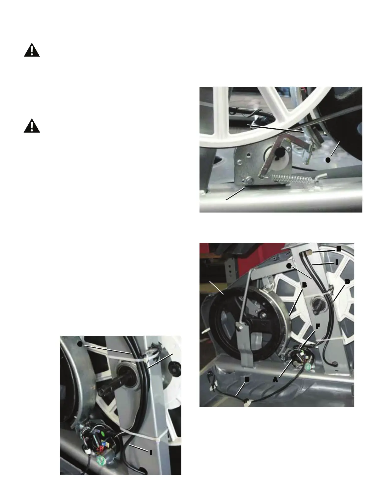
3. Measure and mark the position of the Servo Motor
bracket (A) on the Main Frame.
,QVHUW´[´FDUGERDUGEHWZHHQWKH%UDNH0DJQHW
(B) and the Flywheel (C), and tape the cardboard to the
Brake Magnet.
Note: Be sure the cardboard covers all of the Brake Magnet.
5. Observe the cable routing to the wiring harness (F) on
your machine. Disconnect the Speed Sensor Cable (D) and
Power Inlet Cable (E) from the wiring harness.
6. Tie the length of string to the end of the lower Console
Cable (G) at the top of the Mast mount. Remove the zipties
that attach the lower Console Cable to the Frame. Pull the
cable and string down through the hole (H) on the side of the
)UDPHVRWKDWWKHVWULQJH[WHQGVWKURXJKWKH)UDPH
Note: Do not let the HR and Resistance Cables (I) fall
down inside the Frame.
Disconnect all power to the machine before you service it.
G
D
I
A
B
C
C
E
A
F
D
I
G
H
B

 Loading...