58
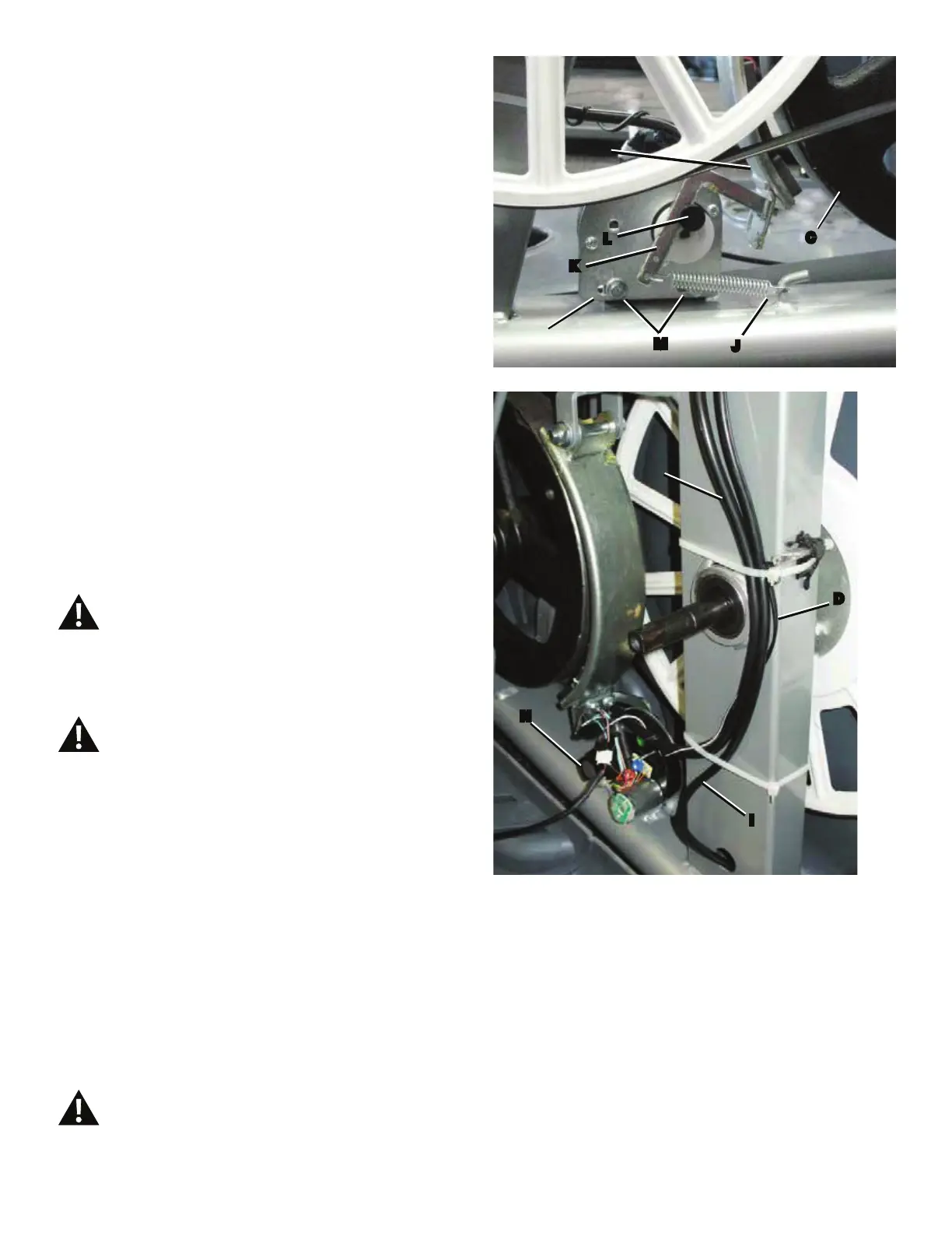
7. Untie the string from the Console Cable (G).
8. Use the pliers to unhook the Tension Spring (J) from
the Main Frame. Pull back and release the Magnet Arm (K)
enough to disengage it from the Motor Pulley Shaft (L).
/RRVHQDQGUHPRYHWKHWZRKH[KHDGEROWV0IURPWKH
Servo Motor (A).
10. Remove the Servo Motor (A). Discard the old Servo Motor.
11. Installation is the reverse procedure. Adjust the new
Servo Motor to same position recorded in Step 3.
NOTICE: Do not touch the Potentiometer (N). Do not
crimp any cables.
12. Tie the end of the string at the hole (H) in the Mast to
the end of the Console Cable (G) on the new Servo Motor
(A). Carefully pull the cable through the hole to the top of the
Mast mount. Untie the string and discard it.
13. Reinstall the Mast, Console and Top Shroud. (Refer to
the “Replace the Shrouds” procedure.) Turn the power on.
0DFKLQHLVRQ&XUUHQWLVDFWLYH7KHUHLVULVNRI
HOHFWULFDOVKRFN
14. Use the console to set the resistance to the highest
level. Unplug the machine.
'LVFRQQHFWDOOSRZHUDQGDOORZWRVLWIRU
minutes.
15. Put the Brake Arm (K) back in position and connect the
Tension Spring (J) with the needlenose pliers.
Note: Before fully attaching the Shrouds, remove the
cardboard from between the Brake Magnet (B)
and the Flywheel (C). Power up the machine to
verify that the Magnet Arm can move freely, and
that the Brake Magnet and Flywheel do not touch
DWWKHPD[LPXPUHVLVWDQFHOHYHO,IQHFHVVDU\
refer to the “Set the Brake Tension” procedure.
16. Final Inspection
Inspect your machine to ensure that all hardware is tight and
components are properly assembled.
Do not use until the machine has been fully
assembled and inspected for correct
SHUIRUPDQFHLQDFFRUGDQFHZLWKWKH2ZQHU¶V
Manual.
L
A
B
C
M
K
J
G
D
I
N