48
NOTICE: It is necessary to remove the Shrouds for this procedure. Refer to the “Replace the Shrouds” procedure.
1RWH<RXUPDFKLQHPD\QRWPDWFKWKHLPDJH)RUUHIHUHQFHRQO\
1. Carefully remove the Left and Right Shrouds. Refer to
the “Replace the Shrouds” procedure in this manual.
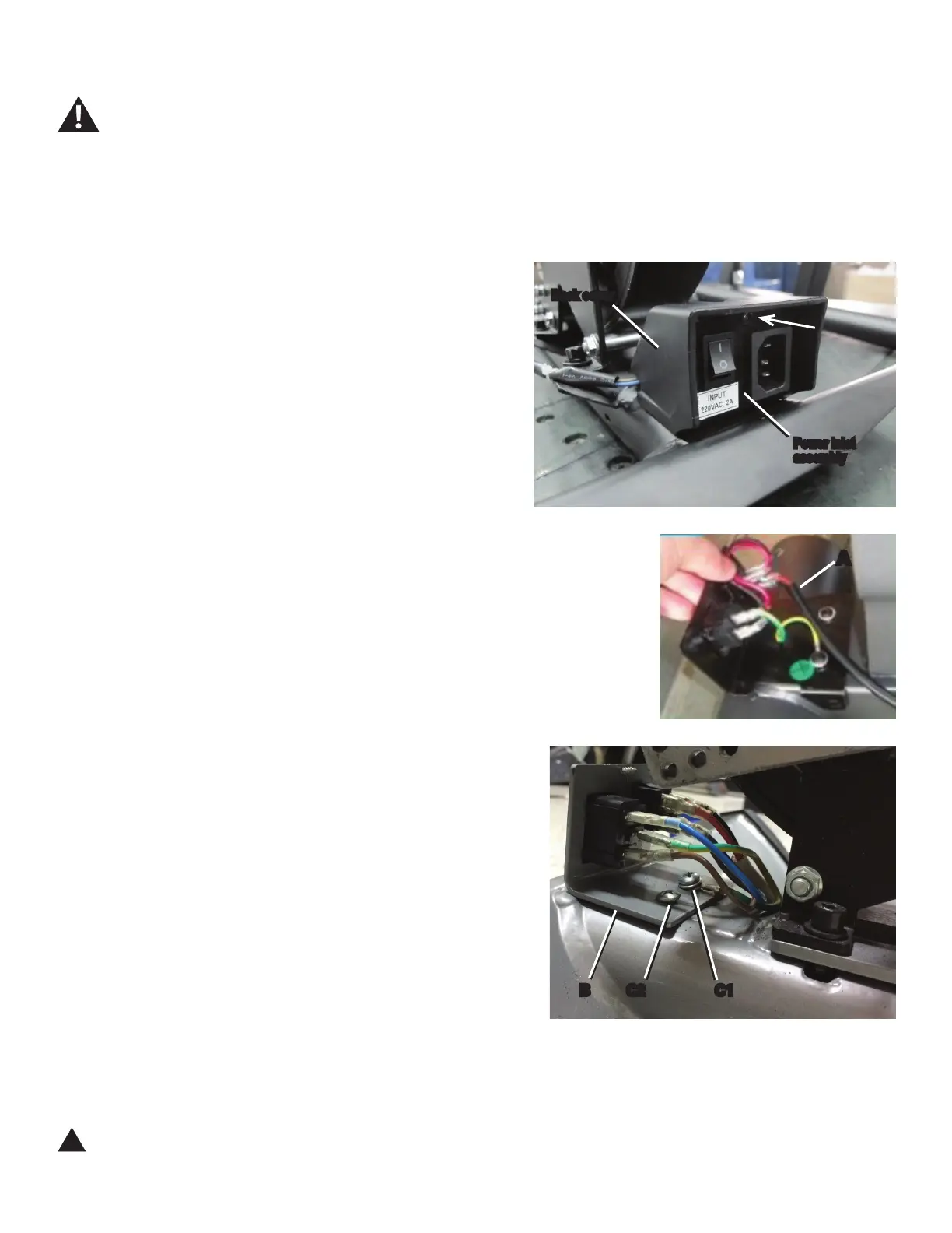
2. Loosen and remove the indicated screw from the Power
Inlet assembly to release the back cover.
3. Carefully disconnect the Power Inlet cable (A) from the
Power Inlet assembly.
4. Loosen and remove the hardware (C1, C2) that attaches
the Power Inlet bracket (B) to the Main Frame. Set the hard-
ware safely aside for reassembly.
5. Remove the old Power Inlet assembly and set it safely
aside.
6. Installation is the reverse procedure.
NOTICE: Use screw C1 to attach the green ground wire
to the bracket and Frame. Be sure not to crimp
any cables.
7. Final Inspection
Inspect your machine to ensure that all hardware is tight and components
DUHSURSHUO\DVVHPEOHG
!
Do not use until the machine has been fully assembled and
inspected for correct performance in accordance with the
Owner’s Manual.
Disconnect all power to the machine before you service it.
Power inlet
assembly
Back cover
A
C1C2B

 Loading...