32 Installing the System Piping
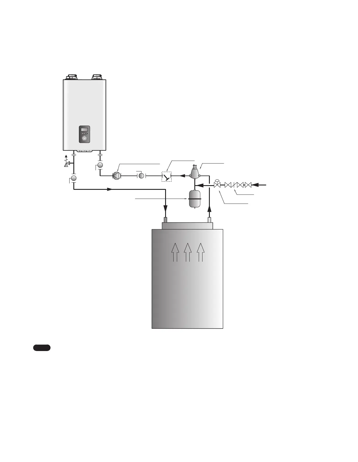
3.5.4 System Application - Air Handler System
Air Flow
Air Handler
System Pump (Boiler Pump)
Make-up Water
Return filter
Expansion Tank
Backflow preventer
Pressure reducing valve
Air Separator
Note
●
System application drawings are intended to explain the system piping concept only.
●
Install a filter in the system return to remove foreign objects from the system. Foreign objects inside the system may result in
abnormal system operation.
●
Refer to “3.3 Filling the System” on page 27 for make-up water connections and refer to the requirements of your local codes
to ensure compliance.
●
Air handlers with an internal pump shall be piped either with a crossover pipe at the AHU or in a primary/secondary
configuration with the boiler.
●
Refer to the “3.6.9 Wiring Diagram - Air Handler” on page 43 for wiring connections.
●
You can use a secondary piping configuration for the air handler system to maintain optimal flow and heat capacity.
 Loading...