1 Installation and Troubleshooting Guide
36
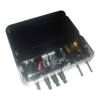
RJ45 Connector
Pin Function Description
1 GND Ground
2 +12/24 V DC Power Output, as per vehicle supply
3 RTS-1 Serial Port 1 (Input) Ready To Send Flow Control
4 RXD-1 Serial Port 1 (Input) Data
5 TXD-1 Serial Port 1 (Output) Data
6 CTS-1 Serial Port 1 (Output) Clear To Send Flow Control
8-Way Expansion Pin Connector
Pin 8-Wire Cable Colour Function Description
1 Black GND Ground
2 White +3.8V DC Reference for Analogue Input
3 Yellow Multi I/O-1
Digital Input OR Digital Output OR Ana-
logue Input 1
4 Green Multi I/O-2
Digital Input OR Digital Output OR Ana-
logue Input 2
5 Light Blue/Black RXD-2 RS232 Serial Port 2 Data Input
6 Light Blue TXD-2 RS232 Serial Port 2 Data Output
7 Orange 1 W+ Temperature Probe Power Supply
8 Orange/White 1 WD Temperature Probe Data
10-Way Expansion Pin Connector
Pin 8-Wire Cable Colour Function Description
1 Black GND Ground
2 Brown TXD-3 RS232 Serial Port 3 Data Output
3 Brown/White RXD-3 RS232 Serial Port 3 Data Input
4 Black GND Ground
5 Purple DI-4
Digital Input 4 (Active High/Low) (also
RPMCount)
6 Blue DI-3
Digital Input 3 (Active High/Low) (also Wake
from Sleep)
7 Blue/White DI-2 Digital Input 2 (Active High/Low)
8 Green/White DI-1 Digital Input 1 (Active High/Low)
9 Light Green DO-1 Digital Output 1 (Active Low only)
10 Grey DO-2 Digital Output 2 (Active Low only)
 Loading...