1 Installation and Troubleshooting Guide
25
1.10 ConEx Sensor Monitoring/Auxiliary Devices
The Qube 300 has 3 serial ports. Use these to connect to other Navman Wireless devices, such
as an M-Nav or MDT, or to third-party equipment for serial capture. The Qube 300 also has sev-
eral digital and analogue I/O lines which can be connected to external sensors or equipment,
using optional I/O cables as follows.
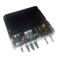
Connection to the serial and digital/analogue I/O is made through the RJ45 Connector (MDT) at
position 1, 8-Way Expansion Pin Connector (I/O-B) at position 3, 10-Way Expansion Pin Con-
nector (I/O-A) at position 4:
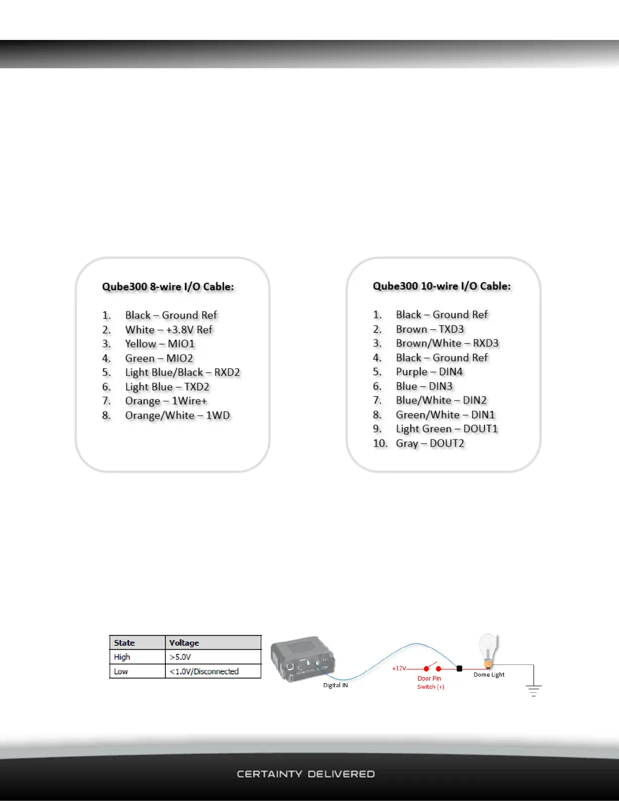
1.10.1 Digital Inputs DI-1 to DI-4
The Digital Inputs can be configured to detect high voltages (Active High) OR low voltages (Act-
ive Low).
Active High Input Configuration
When configured as an Active High Input, the input state is considered ON when it becomes
high. The voltage thresholds that trigger the change in the input state are as follows:
 Loading...