Do you have a question about the NCR RealPOS 5943 and is the answer not in the manual?
Identifies the intended readers of the manual, including installers and engineers.
Outlines compliance with legal requirements and general safety precautions for the product.
Provides warnings and guidance on replacing fuses to prevent fire hazards.
Warns about the explosion risk from incorrect battery replacement and proper disposal.
Directs users to an annex for specific battery disposal instructions in Switzerland.
Specifies suitability for IT power systems with voltage limitations.
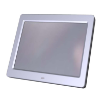
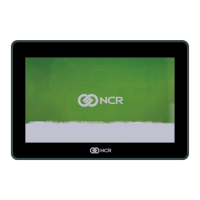
Introduces the NCR 5943 as a 12-inch TFT LCD display and its color options.
Lists the major model numbers and their corresponding descriptions for the display.
Details the host terminals that the 5943 LCD Display is compatible with.
Lists the various display resolutions supported by the NCR 5943.
Describes the key features and components of the 5943 LCD display, including its panel and standards.
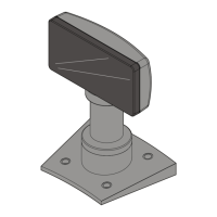
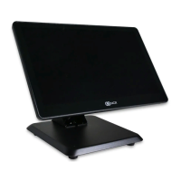
Details the mounting options available for the 5943 LCD display.
Describes the user-accessible controls and indicators for the display.
Explains the function and color indication of the power LED on the display.
Specifies the operating, storage, and transit environmental conditions for the display.
Details the input voltage requirements and specifications for the display.
Provides information on the typical and standby power consumption of the unit.
States the weight of the NCR 5943 LCD display.
Presents the physical dimensions of the LCD display unit.
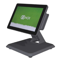
Shows the dimensions and configuration of the display when mounted on a table-top stand.
Introduces the hardware installation process and safety precautions.
Identifies the location of peripheral cable connectors on the display assembly.
Describes the VESA standard mounting pattern and shipped screws for the unit.
Explains how to connect the display to a Point of Sale (POS) terminal.
Details the process for making DVI video connections to the display and terminal.
Details the process for making VGA video connections to the display and terminal.
Explains how to connect the powered USB cable for power to the host terminal.
Guides users on connecting the power brick and AC power cord to the display.
Illustrates proper cable management for different mounting configurations.
Introduces the NCRDDCCI Configuration Utility for adjusting display parameters.
Lists the various display settings that can be adjusted using the utility.
Provides instructions on how to access and launch the NCR Software OSD utility.
Overviews the main interface of the Software OSD utility, including panels and buttons.
Details how to adjust display settings like color using the OSD utility.
Provides step-by-step instructions for detaching the LCD monitor from its mount.
Guides on how to remove the Magnetic Stripe Reader (MSR) component from the unit.
Describes the cover that replaces the MSR if the unit is not configured with one.
Explains the procedure for removing the rear cover of the display unit.
Details the steps to disconnect cables and remove the personality and video boards.
Outlines the process for removing the LCD panel, including the LED harness and lens.
Identifies the components and connectors on the Personality Printed Circuit Board (PCB).
Details the pinout and function for the USB +Power connector.
Identifies the components and connectors on the Video Printed Circuit Board (PCB).
Provides the pinout and function for the VGA video connector.
Provides the pinout and function for the DVI video connector.
Provides instructions for cleaning the display's cabinet and screen safely.
Lists prohibited cleaning agents that can damage the unit.
Details the specific method for cleaning the glass screen to avoid damage.
Explains how to use MSR cleaning and treatment cards for maintenance.
Recommends the frequency for cleaning and treating the MSR based on usage.
| Resolution | 1024 x 768 |
|---|---|
| Brightness | 250 cd/m² |
| Connectivity | VGA, USB |
| Aspect Ratio | 4:3 |
| Touchscreen | Yes |
| Interface | USB |
| Screen Size | 15 inch |
| Mounting | VESA 75mm x 75mm |