7-3
2. Power Circuit
2.1 Power Input
15V & 5V DC input from Power Board through S402 to interface.
The 12V is provide Panel Vcc.
The 5V is provide Flash Memory, and EEPROM.
2.2 DC to DC Circuit
U401 is used generate the system power. It provides low-dropout voltage output 3.3V and 1.8V to provide
Scalar.
U601 is used USB the system power. It provides low-dropout voltage output 3.3V to provide USB.
2.3 Panel Vcc Control
Panel power control used Q401 and U402 from U403 (pin 67) PPWR.
While the PPWR stay at High level; the panel voltage is 3.3V.
While the PPWR stay at Low level; the panel voltage is 0V.
3. Microprocessor Control Circuit
3.1 Clock Circuit
The X401 is crystal; it generates a 14.318MHz output for Scalar IC.
3.2 I
2
C Buses
There are 3 set I
2
C in the circuit:
The first I
2
C is used for Analog EDID in U406 (Pin6: SCL, Pin5: SDA)
And Analog DDC/CI in U403 (Pin77: SCL, Pin78: SDA)
The second I2C is used for Digital EDID in U407 (Pin6: SCL, Pin5 SDA)
The third I2C is used for OSD parameter stored in U403 (Pin92: SCL, Pin93: SDA).
3.3 General-purpose Port
3.3.1 Key Scan Status
U403 pin 81 is for “POWER”
U403 pin 69 is for OSD “MENU/EXIT” adjust
U403 pin 85 is for OSD “SELECT/1 2” adjust
U403 pin 88 is for OSD “RESET” adjust
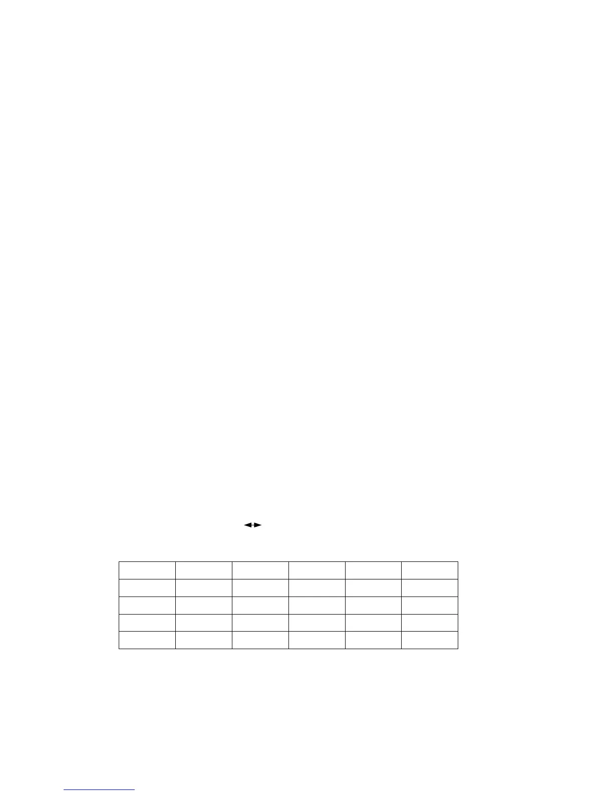
Pin 101 Pin 100 Pin 89 Pin 84
UP v v
DOWN v v
RIGHT v v
LEFT v v