ENG-16
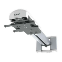
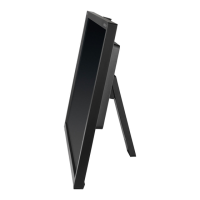
Cap
Fixing screws (B) (two)
Safety lock screws
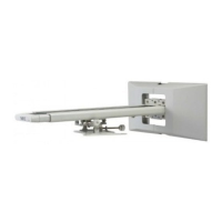
4. Adjust the size of the
projected image.
(1) Loosenthearmunit’stwofixingscrews(B).
(2)Holding theslide arm’s cap,moveforward or back-
ward to project the image over the entire screen.
- When installed following the instructions under
“Projection Distance and Screen Size”, the image
is projected at about the center.
- The slide arm moves a maximum of 422 mm.
- In consideration of change over time of the position
to which the projected image is adjusted, set so
that the projected image is slightly (about 20 mm)
smaller than the screen.
- Do not remove the safety lock screws other than for assembly. Doing so could cause
the slide arm to come off and fall, resulting in injury.
WARNING
Forward Backward
 Loading...