© by NECTA VENDING SOLUTIONS SpA
30
02-2004 184 02
BOILER CONTROL BOARD
This board (see Fig. 21) controls the boiler heating ele-
ment.
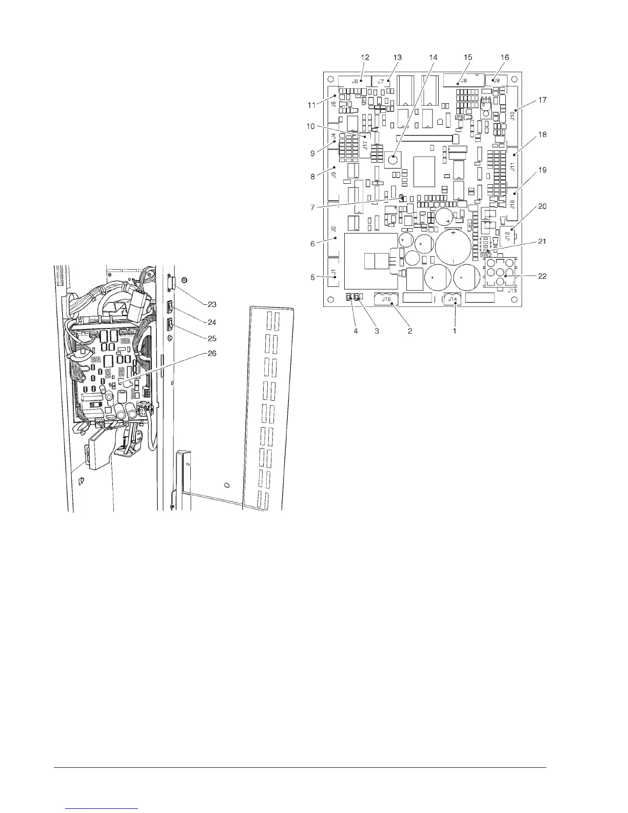
C.P.U. BOARD
The C.P.U. (Central Processing Unit) board controls all
power users set for the maximum configuration and proc-
esses the input signals from the keypad, the payment
system and controls the actuation board.
The Leeds furnish the following indications during the
vending machine operation:
- Green LED (3): blinks during normal operation of the
C.P.U. board;
- Yellow LED (4): glows when 5 V DC are detected;
- Red LED (7): glows when, for any reason, the software is
reset.
Fig. 22
1 - J14 Coin mechanism power supply
2 - J15 Board power supply
3 - Green LED: run (DL2)
4 - Yellow LED: 5 V DC (DL1)
5 - Push-button LED connection- Slider magnet
6 - Not used
7 - Red LED: CPU reset (DL3)
8 - J3 Input/output
9 - J4 Not used
10 - J17 Up Key connector
11 - J5 RS232 cables
12 - J6 Not used
13 - J7 Can-Bus
14 - Button not used
15 - J8 Validators
16 - J9 Not used
17 - J10 LCD display
18 - J11 Keypad
19 - J16 Not used
20 - J12 MDB coin mechanism
21 - Coin mechanism setting minidips (SW2)
22 - J13 Expansion for BDV / EXE
23 - RS232 serial port
24 - Wash button
25 - Programming button
26 - C.P.U. board