VP1007-B / Installation manual
Version 01.000 / November 2020 / EN
8
Livestock Management
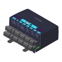
Connector Symbol Description
Vout + Output voltage 25 VDC, ± 20%
– Minus
+ Input voltage 25 VDC, ± 20%Vin
– Minus
C
H
CAN high (cable twisted pair with C
L
)
C
L
CAN low (cable twisted pair with C
H
)
CAN
CAN bus cable shielding
~ Antenna synchronization, AC (no plus or minus, cable must be twisted pair)SYNC in
~ Antenna synchronization, AC (no plus or minus, cable must be twisted pair)
~ Antenna synchronization, AC (no plus or minus, cable must be twisted pair)SYNC out
~ Antenna synchronization, AC (no plus or minus, cable must be twisted pair)
I/O 1/2/3/4/5 + Output max. 2 A (total of all outputs 4 A)
O Output max. 2 A (total of all outputs 4 A)
I Input
– Minus for output (O) and minus input (I)
COMM B- Receive data (RS-485)
A+ / RxD A+ = Send data (RS-485) / RxD = Receive data (RS-232)
TxD Send data (RS-232)
/ – Shield (RS-485) / minus (RS-232)
ANT. 1 + Plus (core of coax cable or plus of antenna cable)
FI Frequency synchronization (of the antenna signal) in (must be connected to the
FSYNC-O connector of the other V-pack)
– Minus (shield of coax cable or minus of antenna cable)
ANT. 2 + Plus (core of coax cable or antenna cable)
FO Frequency synchronization (of the antenna signal) out (must be connected to
the FSYNC-I connector of the other V-pack)
– Minus (shield of coax cable or antenna cable)
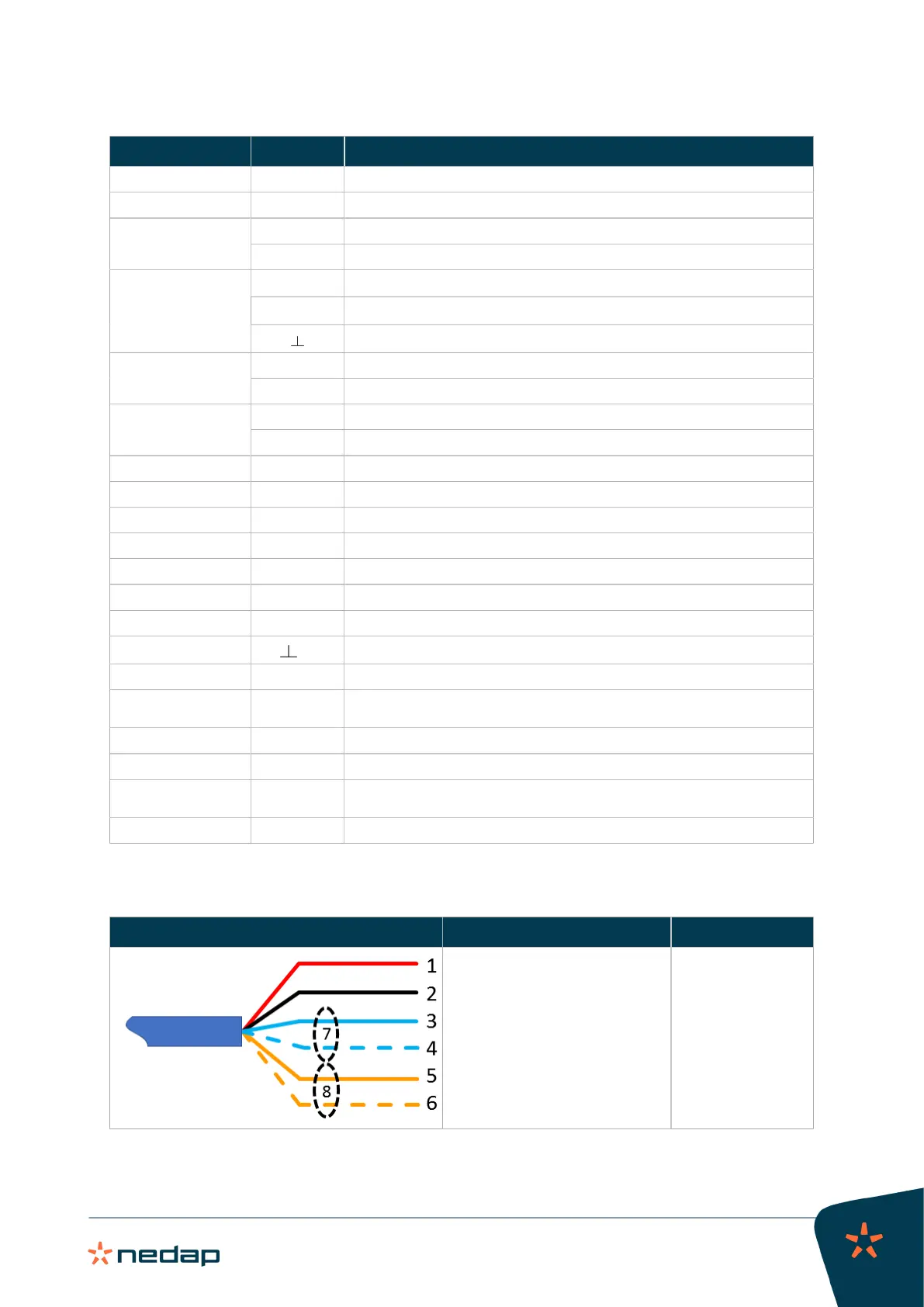
Velos CAN cable
Velos CAN cable Wiring Wire color
1. Power +25 Vdc
2. Power –
3. CAN
High
4. CAN
Low
5. HF synchronization
6. HF synchronization
7. Shield communication wires
8. Shield synchronization wires
1. Red
2. Black
3. Blue
4. Blue/white
5. Orange
6. Orange/white
7. Blank
8. Blank