VP1007-B / Installation manual
Version 01.000 / November 2020 / EN
9
Livestock Management
Caution
• The maximum number of V-packs that can be installed per CAN channel of the VPU depends on the
power consumption.
•
.
The maximum CAN cable length between the VPU and the last V-pack is 80 m (262 ft) with 1.5 mm
2
(0.0023 in.
2
) cable and 100 m (328 ft) with 2.0 mm
2
(0.0031 in.
2
) cable.
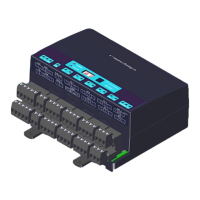
3.3.1 Wiring diagram VP1007-B
Figure1:Wiring diagram VP1007-B example
1. Velos CAN cable OUT (to next V-pack) 5. Antenna
2. Velos CAN cable IN (from VPU or previous V-pack) 6. Signal light
3. Switch Wiring colors: see Wiring color coding (page 28)
4. Feed motor
1. Install all wiring according to the VP1007-B wiring diagram. An example of a VP1007-B wiring diagram is
shown in Figure 1 (page 9).
If the VP1007-B is part of a complete Nedap system, use the installation manual of this system. The
installation manual can be obtained from your dealer or on our Business portal: http://www.nedap.com/
livestockmanagement-portal.
2. The SYNC connector is used for the synchronization of the ISO identification between more than one ISO
transceiver, such as the VP1007-B:
– The SYNC connection is mandatory when using the ISO mode of the VP1007-B
– When using FDX only it is not necessary to connect the synchronization cable.