17
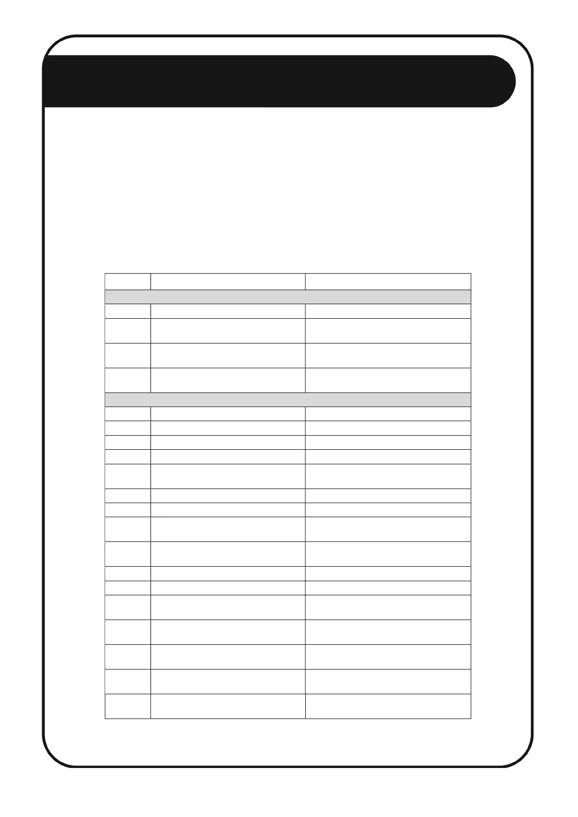
The following tables detail the error/alarm codes that can be generated in the
history (see section 5.2.4 & 5.2.5). The second digit from the right represents the
communication error and the last digit represent the Taut Wire sensor alarm, in hex
format. If more than one error and/or alarm have been generated, the second digit
from the right will be an accumulation of all errors and the last digit will be an
accumulation of all alarms. For example, if a sensor left and sensor right alarm
occurred, the digit will be 2 + 1 = 3. The following table displays the error digit and
alarm digit of the error code:
Digit Description Solution
Communication Errors (second digit from right)
0 No Communication Error
1 Communication Error Unstable communication to sensor.
Check connections and wiring.
2 Communication Fail Error Sensor communication lost. Check
connections and wiring.
3 Communication Error and
Communication Fail Error
Unstable communication to sensor.
Check connections and wiring.
Sensor Alarms (last digit)
0 No Sensor Alarms
1 Sensor Right* Check intrusion
2 Sensor Left* Check intrusion
3 Sensor Left and Right* Check intrusion
4 Service Right* Sensor at stress limit to right.
Reset tension on sensor.
5 Sensor and Service Right* Check intrusion, reset tension on sensor
6 Sensor Left and Service Right* Check intrusion, reset tension on sensor
7 Sensor Left and Right and Service
Right*
Check intrusion, reset tension on sensor
8 Service Left* Sensor at stress limit to left.
Reset tension on sensor.
9 Sensor Right and Service Left* Check intrusion, reset tension on sensor
A Sensor Left and Service Left* Check intrusion, reset tension on sensor
B Sensor Left and Right and Service
Left*
Check intrusion, reset tension on sensor
C Service Left and Right Unstable communication to sensor.
Check connections and wiring.
D Sensor Right, Service Left and Right Unstable communication to sensor.
Check connections and wiring.
E Sensor Left, Service Left and Right Unstable communication to sensor.
Check connections and wiring.
F Sensor Left and Right, Service Left
and Right
Unstable communication to sensor.
Check connections and wiring.
*Sensor mounted with NEMTEK logo on top and wire clamp facing towards installer
Appendix A: Error/Alarm Codes