4.3 Power Supply Installation B
7
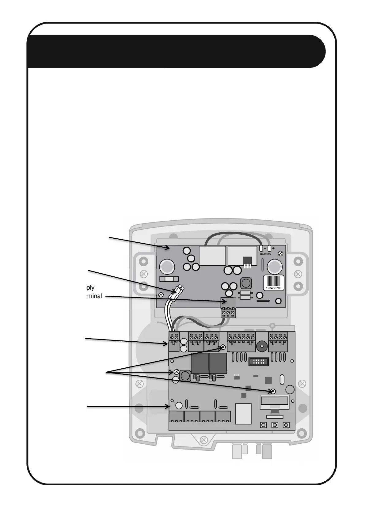
• Ensure mains power and battery are disconnected.
• Place the Node board PCB (1) as shown in the diagram, ensuring that the 3
mounting holes (2), align with the screw holes in the power supply unit.
• Connect the Node board to the power supply PCB (3) by using the Node input
(4) and power supply output (5) terminals. Take care to use the 12 V supply
output and make sure of the polarity as indicated on the PCB!
• On the power supply unit without a mains transformer, connect the mains
transformer to the 16 Vac input terminal (6) of the power supply, by using the
supplied pigtail wire with connectors.
• Reconnect the battery and fit the cover of the power supply before
reconnecting the mains supply.
3. Power Supply PCB
6. Mains Input
Connector
5. Power Supply
Output Terminal
4. Node Input
Terminal
2. Mounting Holes
1. Taut Wire
Node PCB