EasyManuals Logo

Neoway N21 Series User Manual

Neoway N21 Series
47 pages
To Next Page IconTo Next Page
To Previous Page IconTo Previous Page
Page #23 background imageLoading...
Page #23 background image
N21
Hardware User Guide
Copyright © Neoway Technology Co., Ltd. All rights reserved.
14
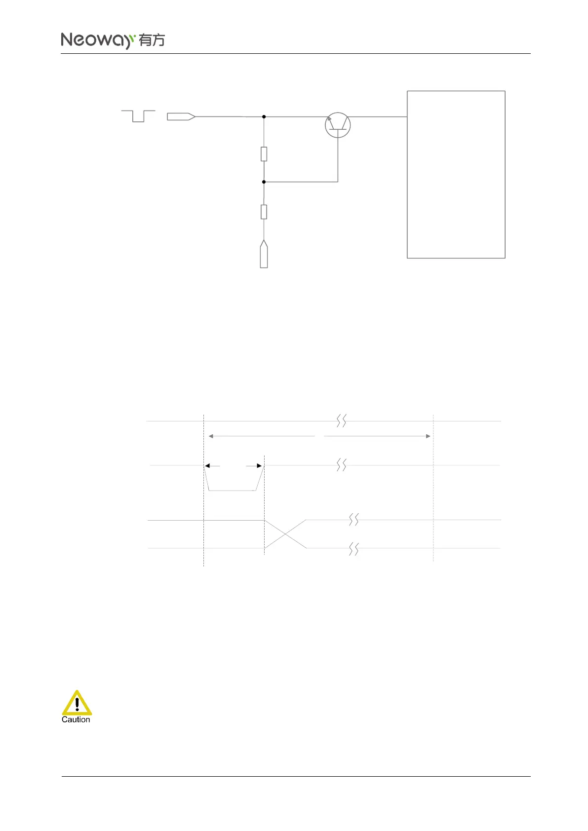
Figure 3-9 Reset circuit with triode separating
R2
VDD_EXT
MCU_RESET
N21 module
RESET_N
Q1
R1
To reset the module through high level, refer to Figure 3-4.
In Figure 3-9, VDD_EXT=3.3V, R1=47 k, R2=4.7 k. 2.8V is recommended for supply voltage at the
base of Q1.
Figure 3-10 shows the reset timing of N21.
Figure 3-10 Reset timing of N21
VBAT
2
s
Inactive
Active
200ms
RESET_N
UART
3.3 Peripheral Interfaces
N21 provides various peripheral interfaces.

Table of Contents

Questions and Answers:

Question and Answer IconNeed help?

Do you have a question about the Neoway N21 Series and is the answer not in the manual?

Neoway N21 Series Specifications

General IconGeneral
BrandNeoway
ModelN21 Series
CategoryControl Unit
LanguageEnglish

Related product manuals