Copyright © Neoway Technology Co., Ltd. All rights reserved.
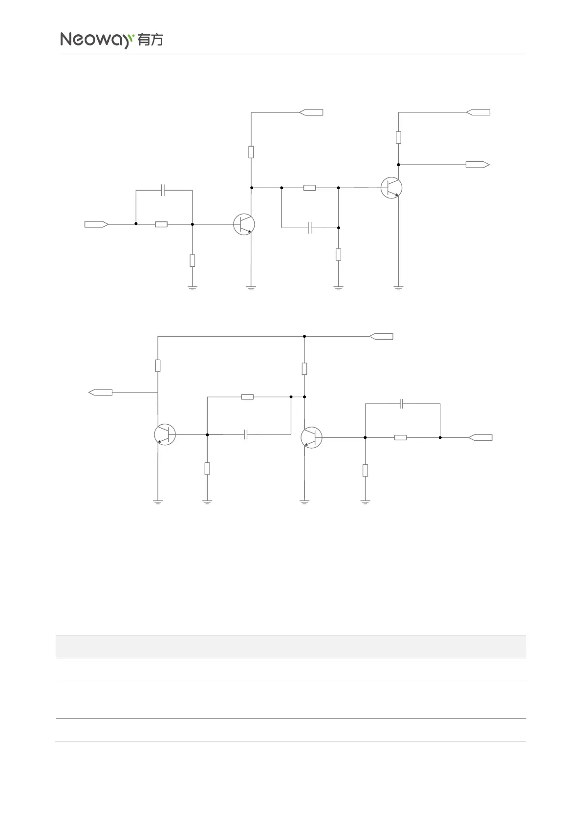
Figure 3-14 Recommended level shifting circuit 3
C1
C2
220pF
UART_RXD
10 kΩ
10 kΩ
4.7 kΩ
VDDIO_2P8
4.7 kΩ
220pF
47 kΩ
4.7 kΩ
Q1
Q2
MCU_TXD
R4
R1
R6
R5
R2
R3
C1
C2
220pF
UART_TXD
10 kΩ
R2 47
kΩ
4.7 kΩ
VDDIO_2P8
2.2 kΩ
220pF
47 kΩ
4.7 kΩ
Q1
Q2
MCU_RXD
VCC_IO
R4
R1
R5
R6
R3
Q1, Q2: MMBT3904 or MMBT2222. High-speed transistor is better.
MCU_TXD and MCU_RXD are respectively the TX and RX of the MCU while UART_TXD and
UART_RXD are respectively the TX and RX of the module. VCC_IO is the IO voltage of the MCU.
3.3.2 USIM
Compatible with 1.8 V/3 V USIM card
A 10 kΩ resistor is required between
USIM_VCC and USIM_DATA.

 Loading...