Copyright © Neoway Technology Co., Ltd. All rights reserved.
In all reference designs of this section, the signals of pins on the module is named in perspective of
module while peripheral pins are named from the view of the components. For example, UART_TXD
indicates the pin that the module sends data while MCU_RXD indicates the pin that MCU receives data.
These two pins should be connected.
Please note the signal naming of pins on the components in peripheral selection and design.
3.3.1 UART
N21 provides one UART interface that supports automatic baud rate detection. The level at the UART
interface is 2.8V.
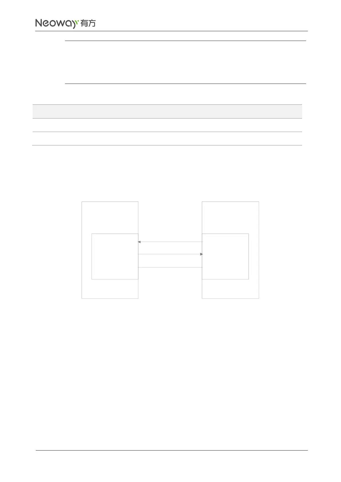
Figure 3-11 UART connection
UART_RXD
UART_TXD
MCU_TXD
MCU_RXD
GND GND
N21
module
Client
Schematic Design Guidelines
Note the match of signals.
If the UART does not match the logic voltage of the MCU, add an external level shifting circuit.
Three types of level shifting circuit are recommended based on the logic level quality. The first one is
preferred and the other two are cost-effective simple circuits. Note their application senarios.
Level shift chip is recommended if the level of MCU is higher than 3.3V or the baudrate is higher than
1 MHz. Figure 3-12 shows the reference design.

 Loading...