Copyright © Neoway Technology Co., Ltd. All rights reserved.
3.5 Other Interfaces
3.5.1 WAKEUP
This pin is used to wake up N21 from PSM mode. After N21 enters PSM mode, input high level at
WAKEUP pin for more than 1 second to wake up the module to send data. However, the module will
not register with networks proactively after wake up. Therefore, users need to send a data transmitting
request. For details, see Neoway_N21_AT_Command_Manual.
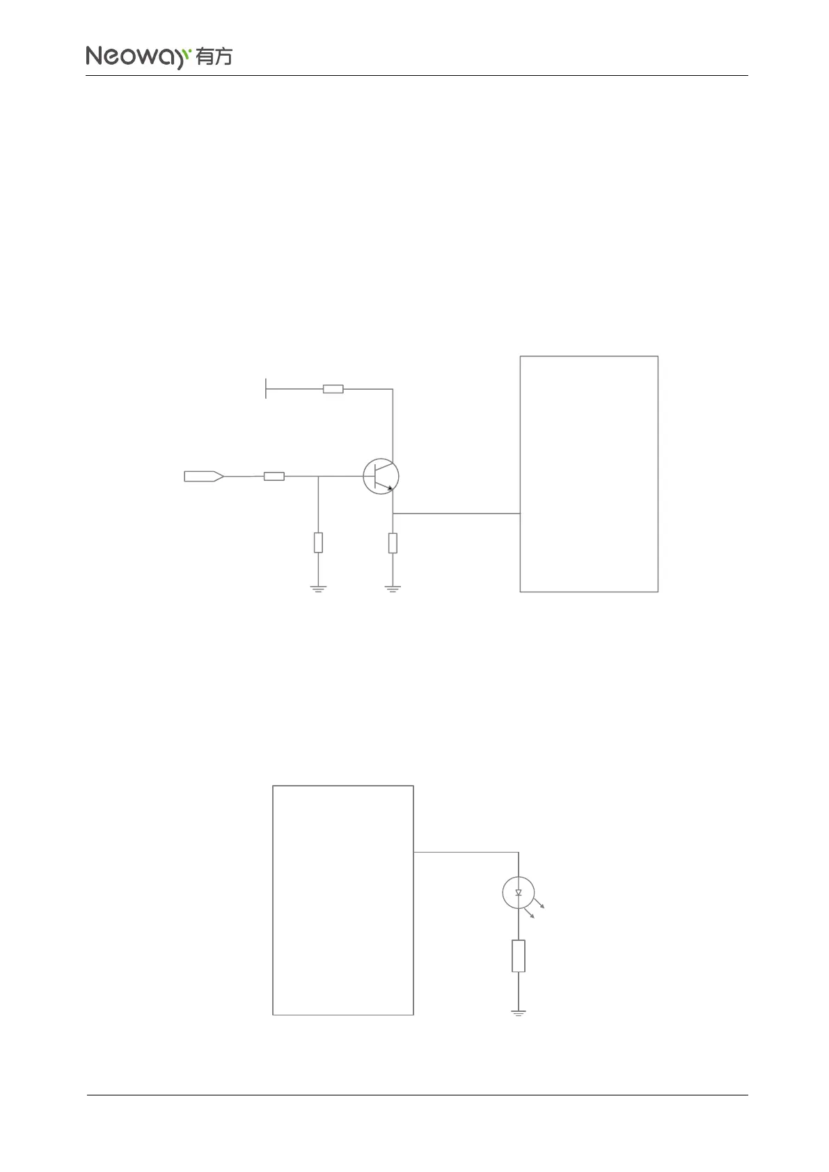
Figure 3-22 shows the reference design of WAKEUP pin.
Figure 3-22 Reference design of WAKEUP
2 kΩ
WAKEUP
N21
Module
1KΩ
MCU_WAKEUP
VCC_3P3
10KΩ
4.7KΩ
3.5.2 NET_LIGHT
NET_LIGHT outputs a high level of 2.8V and a maximum driving current of 4 mA.
High level is allowed to drive a common LED indicator directly. See Figure 3-23.
Figure 3-23 Driving LED directly

 Loading...