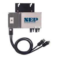
Step 2 – Connect the Wiring Harnesses
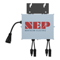
Each BDM-600 comes with an integrated trunk cable to simplify the AC
connecon process. The AC trunk cable includes a male connector on one end
and a female connector at the other end. Plug the male AC connector of the rst
BDM-600 into the connector on the tail cable. Plug the female AC connector of
the rst BDM-600 into the male connector of the next BDM-600 (or jumper
cable) and connue this “daisy chain” process to form a connuous AC branch
circ
uit. Terminate the nal female connector on the last microinverter in the
branch circuit with the protecve cap. The connectors are keyed with a snap lock
pin. A “click” indicates proper mang. Secure the mated connector pairs and any
excess AC cable to the rail or racking using cable clips or wire es
WARNING:
DO NOT EXCEED THE MAXIMUM NUMBER OF SEVEN (7) BDM-600s IN A
240V AC BRANCH CIRCUIT (SIX(6) FOR 208V) AND EACH BDM-600 AC BRANC
H CIRCUIT
MUST BE SOURCED FROM A 20A MAXIMUM BREAKER.
Install a protecve end cap on the open female AC connector on the last
microinverter at the end of the truck cable.
WARNING:
MAKE SURE PROTECTIVE END CAPS HAVE BEEN INSTALLED ON ALL UNUSED
AC CONNECTORS. UNUSED AC BDM-600 WIRE HARNESS CONNECTORS ARE LIVE WHEN
THE SYSTEM IS ENERGIZED BY T
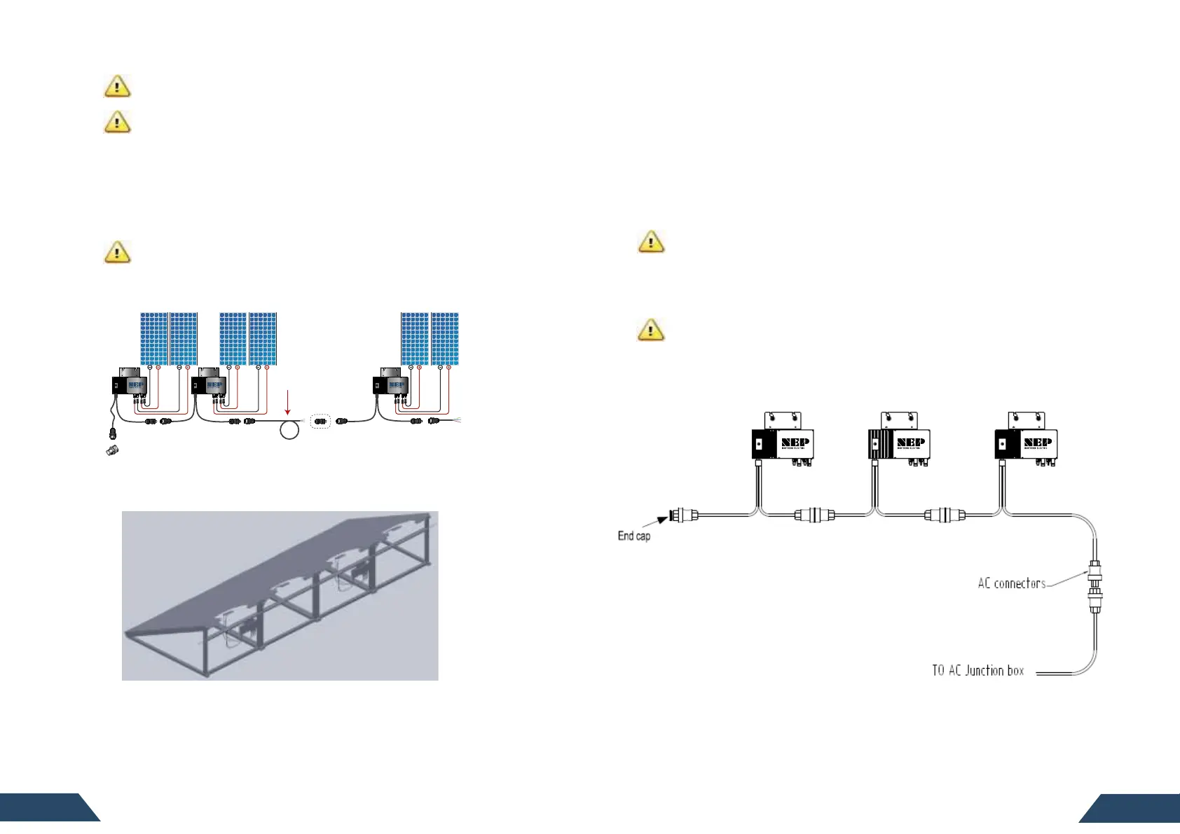
The AC branch circuit should look as pictured below:
WARNING: CONNECT BDM-600S TO THE ELECTRICAL UTILITY GRID ONLY AFTER RECEIVING
PRIOR APPROVAL FROM THE UTILITY COMPANYAND LOCAL AHJ.
WARNING: BE AWARE THAT ONLY QUALIFIED PERSONNEL CAN CONNECT BDM-600 TO
THE ELECTRICAL UTILITY GRID.
Step 1 – System Layout
Mark the approximate locaon of each pair of PV modules on the racking system.
Place the microinverters at the locaon called out in the layout map and loosely
to the rails using the MLPE clam
ps. Check the reach of all DC and AC
cabling. DC jumpers may be required for some modules. Reposion as needed.
WARNING:
ALLOW A MINIMUM OF 2.75 INCHES BOTH BETWEEN THE TOP OF THE
ROOF AND THE BOTTOM OF THE BDM-600 AND BETWEEN THE BACK OF THE PV MODULE
AND THE TOP OF THE BDM-600. DO NOT PLACE THE BDM-600 IN A LOCATION SUBJECT TO
DIRECT SUNLIGHT.
For ground mount, ballasted, or at roof deployments it may be necessary to
the microinverters to the racking frame.
Once thenal posion is conrmed, secure the microinverters using the MLPE
clamps and torque per the manufacturer’s specions. Typical values are about
lbs (16.3 NM).
JUMPER
“Optional, to connect
separate array”