Step 3 – Install the AC Branch Circuit Junc�on Box
1. Install an appropriate juncon box on to the mounng plate.
2. Mount the adapter plate at a suitable locaon on the racking or frame. This
is typically near the end of a row of modules.
3. Feed the open wire end of the tail cable into the juncon box and secure with
an appropriate cord grip or strain relief ng. The AC tail cable requires a
strain relief connector with an opening of 3/8” in diameter.
4. Feed the connecng wires from either the main se
rvice panel or subpanel (if
mulple branch circuits are deployed) into the juncon box. This is most likely
via metal conduit.
5. Connect L1, L2 and Ground from the branch circuit to their corresponding
connecons from the electrical panel with wire nuts. NEP recommends the
applying sealant to the inside cavity of the wire nuts. Seal the juncon box.
Step 4 – Ground the System
Each BDM-600 has an integrated ground protecon circuit. The grounding wire is
through the trunk cable, and should be securely connected to the ground
connector in the juncon box.
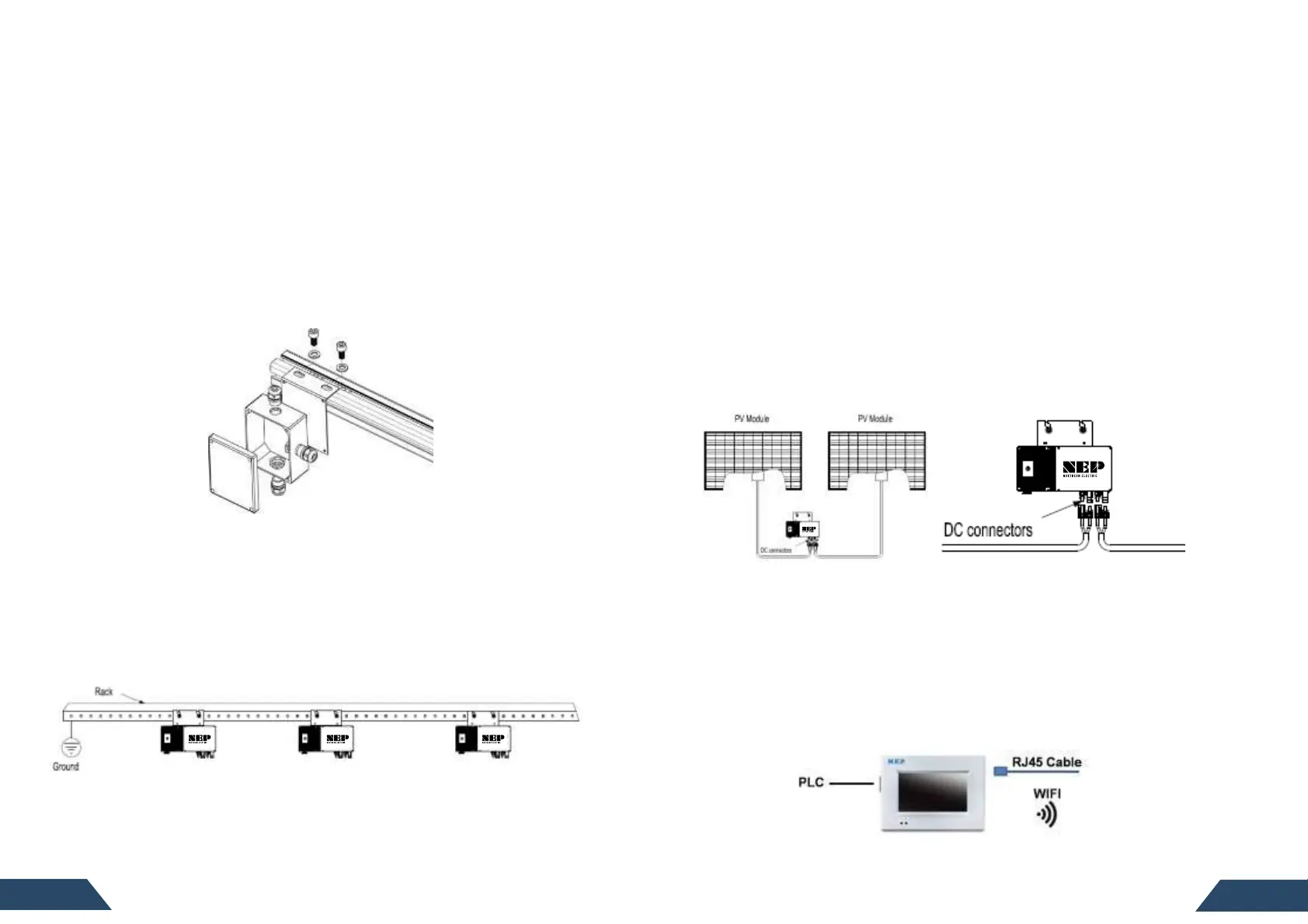
Ground the System Through Racking (Op�on)
BDM-600 may also be grounded through the racking as shown below.
Step 5 – Complete the Connec�on Map
Each BDM-600 has a removable serial number label located on the mounng plate
as well as addional sckers included in the microinverter’s protecve bag.
Remove one and ax it to the corresponding locaon on the layout map. Aer
entering this data, the BDM-256 will create a virtual array from the map you create.
Step 6 – Connect the PV Modules
Connect all AC all system inter-wiring connecons prior to installing the PV
modules.
1. Mount the PV modules in the posio
ns corresponding to their associated
BDM-600 microinverter. Each BDM-600 comes with two sets of oppositely sexed
DC connectors.
2. Connect the posive DC wire from the rst PV module to the negavely marked
DC connector (male pin)on the BDM-600. Then connect the negave DC wire
from the PV module to the positively marked DC connector (female socket) of
the BDM-600. Next, do the same for the second set of DC connectors from the
second module. Repeat for all re
maining PV modules using one BDM-600 for
each set of modules. If the system contains an odd number of modules, it is
acceptable to connect only one PV module to the BDM-600.
Step 7 – Install the Monitoring Gateway
The BDG-256 (or BDG-256P3) is a versale gateway that connects each of the
BDM-600 microinverter to the NEP server via the cloud, allowing for collecon of
producon and other data useful in system monitoring and trouble shoong. It is
easily insta
lled either by plugging into an exisng 120V AC interior outlet or by
hardwiring into the 240V service in a suitable protecve enclosure. Connecng to
240V will maximize the strength of the PLC signal, thereby improving
communicaon. The BDG-256P3 is designed to support commercial three phase
systems and should only be located in a protecve enclosure. The gateway then
will connect to the server via either WiFi or direct Ethernet connecon.
Follow the instrucons in the NEP Gateway BDM-256/256P3 Installaon and
Operaons Manual for specidetails on registering the individual microinverters
in the PV system.