Table 3. LEDs on the front panel of model GC728XP (Continued)
DescriptionLED
Off. No SFP module link is established.
Solid green. A valid 1 Gbps link is established.
Blinking green.The SFP fiber port is transmitting or receiving packets at 1 Gbps.
Link/ACT LED
Link and activity for SFP fiber ports
25F and 26F
Off. No SFP+ module link is established.
Solid amber. A valid 1 Gbps link is established.
Blinking amber.The SFP+ fiber port is transmitting or receiving packets at 1 Gbps.
Solid green. A valid 10 Gbps link is established.
Blinking green.The SFP+ fiber port is transmitting or receiving packets at 10 Gbps.
Link/ACT LED
Link and activity for SFP+ fiber
ports 27F+ and 28F+
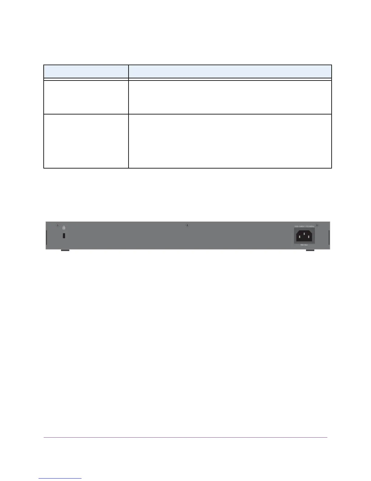
Back Panel
The back panel contains a Kensington lock for an optional security cable and an AC power connector. Both
models integrate an internal power supply, require AC power, and come with a power cord.
Figure 3. Back panel
Switch Hardware Interfaces
The following sections describe the hardware interfaces on the switch.
RJ-45 Ports for 10/100/1000M BASE-T Ethernet Connectivity
All RJ-45 copper ports support autosensing. When you insert a cable into an RJ-45 port, the switch
automatically ascertains the maximum speed (10 Mbps, 100 Mbps, or 1 Gbps) and duplex mode (half-duplex
or full-duplex) of the attached device. All ports support a Category 5e (Cat 5e) cable (or higher-rated Ethernet
cable) terminated with an 8-pin RJ-45 connector.
To simplify the procedure for attaching devices, all RJ-45 ports support Auto Uplink technology.This
technology allows attaching devices to the RJ-45 ports with either straight-through or crossover cables.
Hardware Overview
14
Insight Managed 28-Port Gigabit Ethernet (PoE+) Smart Cloud Switch
 Loading...