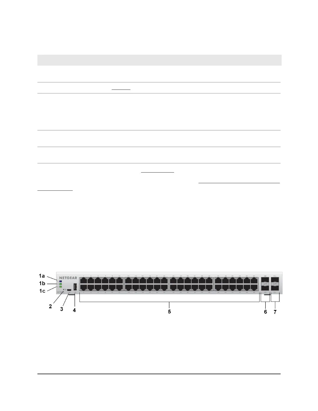
Table 1. Front panel components (Continued)
DescriptionNumber
One micro USB console and debug port. Use this port only as directed and assisted by technical
support.
3
USB 2.0 port (see USB Port on page 21)4
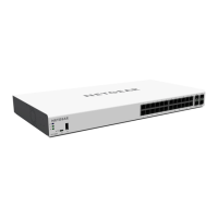
Model GC728X. Twenty-four independent 10/100/1000BASE-T RJ-45 ports, numbered 1 through
24. Each port provides one LED that functions as the combined speed and activity LED.
Model GC728XP. Twenty-four independent 10/100/1000BASE-T RJ-45 PoE+ ports, numbered
1 through 24. Each port provides a left LED that functions as the combined speed and activity LED
and a right LED that indicates the PoE status.
5
Two dedicated Gigabit SFP fiber ports, numbered 25F and 26F, that can accept optional transceiver
modules. Each port provides a single LED that functions as the combined link and activity LED.
6
Two dedicated 10G SFP fiber ports, numbered 27F+ and 28F+, that can accept optional transceiver
modules. Each port provides a single LED that functions as the combined link and activity LED.
7
For information about the LEDs, see Status LEDs on page 16.
For information about optional transceiver modules, see SFP and SFP+ Ports for Fiber
Connectivity on page 21.
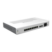
Front Panel Models GC752X and GC752XP
Model GC752X provides 48 10/100/1000BASE-T RJ-45 ports, 2 dedicated Gigabit SFP
fiber ports, and 2 dedicated 10G SFP+ fiber ports
Model GC752XP provides 48 10/100/1000BASE-T RJ-45 PoE+ ports, 2 dedicated Gigabit
SFP fiber ports, and 2 dedicated 10G SFP+ fiber ports.
The following figures show the front panels.
Figure 3. Front panel model GC752X
Hardware Installation Guide15Hardware Overview
Insight Managed 28-Port and 52-Port Gigabit Ethernet (PoE+) Smart Cloud Switch
 Loading...