EasyManuals Logo
Home>NETGEAR>Switch>M4100 Series

NETGEAR M4100 Series Hardware Installation Guide

NETGEAR M4100 Series
34 pages
To Next Page IconTo Next Page
To Previous Page IconTo Previous Page
Page #5 background imageLoading...
Page #5 background image
5
NETGEAR Managed Switch
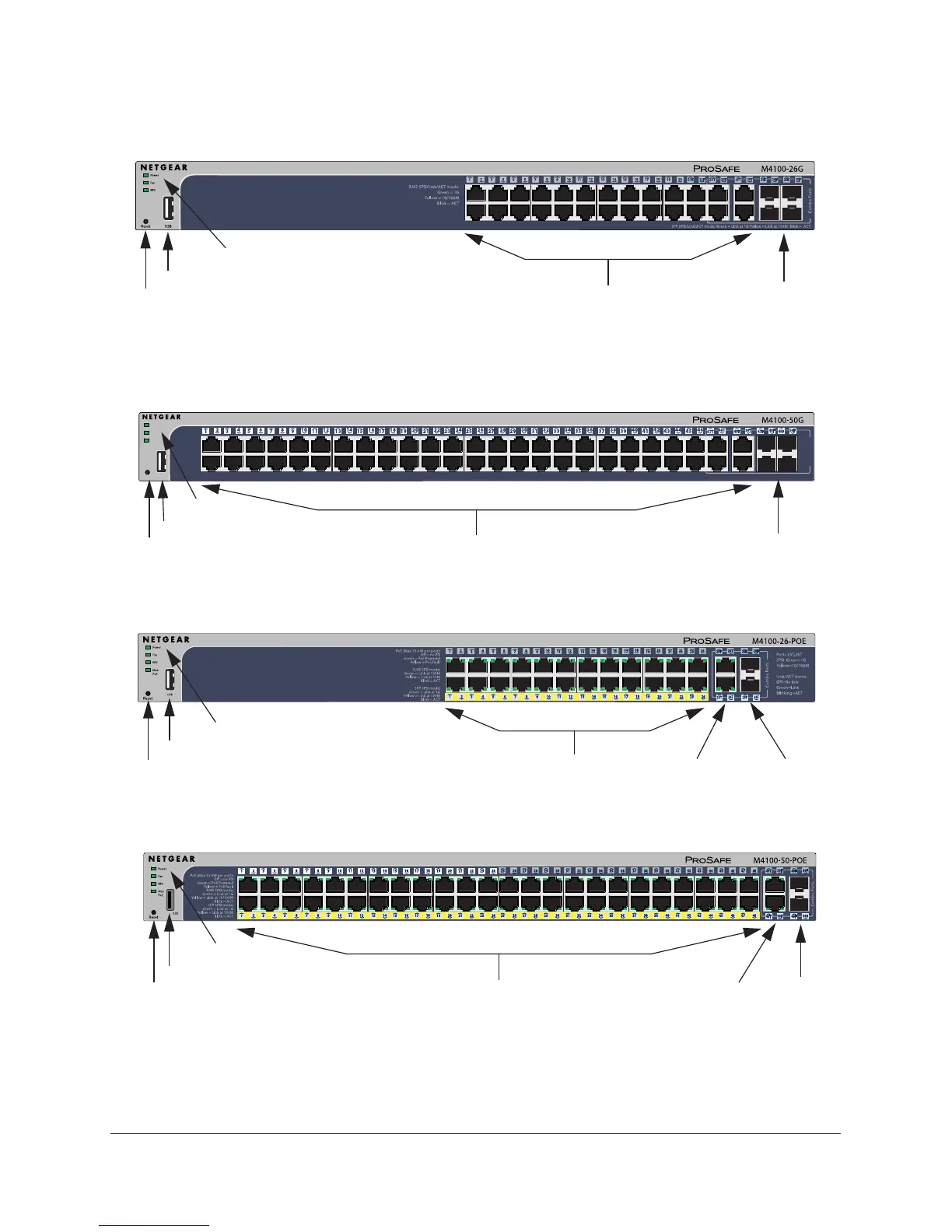
Figure 1. M4100-26G front panel
Figure 2. M4100-50G front panel
LEDs
Reset button
SFP ports
POE ports
USB port
RJ-45 ports
Figure 3. M4100-26-POE front panel
Reset button
LEDs
USB port
POE ports
SFP ports
RJ-45 ports
Figure 4. M4100-50-POE front panel
LEDs
Reset button
SFP ports
RJ-45 ports
USB port
Combo Ports
RJ45 SPD/Link/ACT mode: Green = 1G Yellow = 10/100M Blink = ACT
SFP SPD/Link/ACT mode: Green = Link at 1G Yellow = Link at 100M Blink = ACT
Power
Fan
RPS
Reset
USB
LEDs
Reset button
RJ-45 ports
USB port
SFP ports

Other manuals for NETGEAR M4100 Series

Questions and Answers:

Question and Answer IconNeed help?

Do you have a question about the NETGEAR M4100 Series and is the answer not in the manual?

NETGEAR M4100 Series Specifications

General IconGeneral
BrandNETGEAR
ModelM4100 Series
CategorySwitch
LanguageEnglish

Related product manuals