Do you have a question about the NETGEAR M4500 Series and is the answer not in the manual?
Information on regulatory compliance and conformity for NETGEAR products.
Lists NETGEAR's trademarks and mentions other trademarks used for reference.
Details previous versions of the publication, including part numbers and publish dates.
Guidelines for indoor use, service markings, and general safety measures.
Importance of using the correct power source and setting the voltage selector.
Ensuring correct device rating, cable usage, and proper grounding.
Recommendations for surge protection, cable routing, and avoiding modifications.
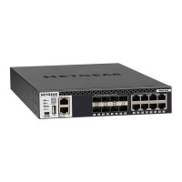
Details of the switch chassis and its front panel components.
Identification of front panel components and their LED indicators.
Identification of rear panel components including power supply units.
Explanation of the system status LEDs on the M4500-48XF8C.
Explanation of the port status LEDs on the M4500-48XF8C.
Description of port types, speeds, and QSFP28 fan-out capabilities.
List of supported transceivers and direct-attach cables for data ports.
Step-by-step instructions for installing SFP28 and QSFP28 modules.
Description of the fan trays and power supply units (PSUs).
Explanation of PSU LED status and illustration of airflow direction.
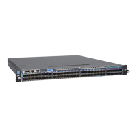
Details of the switch chassis and its front panel components.
Identification of rear panel components including power supply units.
Explanation of the system status LEDs on the M4500-32C.
Explanation of the port status LEDs on the M4500-32C.
Description of port types, speeds, and QSFP28 fan-out capabilities.
List of supported transceivers and direct-attach cables for data ports.
Description of the fan trays and power supply units (PSUs).
Explanation of PSU LED status and illustration of airflow direction.
Instructions for unpacking the switch and conducting a site survey.
Guidelines for ventilation, switch positioning, and rack mounting.
Steps for preparing and installing the rack mounting rails.
Connecting to the console port and console cable wiring specifications.
Instructions for connecting to the switch's management port.
Connecting the power cord and details about AC power supply.
Troubleshooting common issues with indicators, power, and cooling.
Network access methods and procedure for replacing power supply units.
Step-by-step instructions for replacing the switch's fan trays.
| Series | M4500 |
|---|---|
| Managed | Yes |
| L3 | Yes |
| Rack Mountable | Yes |
| Layer | L3 |
| Management | SNMP |
| Dimensions (W x D x H) | Varies by model |
| Weight | Varies by model |
| AC Power Supply | Yes |
| Operating Temperature | 0°C to 50°C |
| Storage Temperature | -20°C to 70°C |