Hardware Installation
NETGEAR M4500 Series Switches Hardware Installation Guide 30
2 Connect the other end of the Ethernet cable to a network.
The Management port LED (Link/Activity LED) lights green when the network link is
established.
Connecting the Power
CAUTION
Ensure that the socket outlet is installed near the equipment and be easily
accessible.
The power cord must have safety ground pin or contact that is suitable for the
electrical outlet.
The power supply cord(s) must be plugged into socket outlet(s) that is/are
provided with a suitable earth ground.
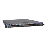
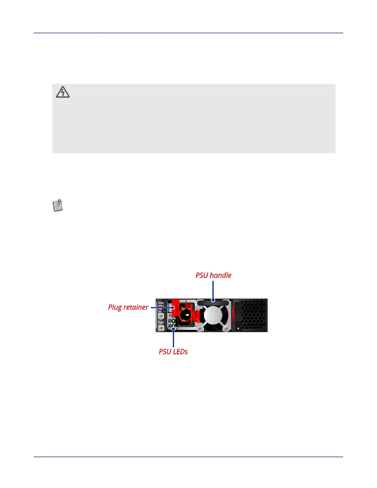
AC Power Supply
The switch is equipped with two slots for power supplies. Depending on your needs, you may
opt to use one or both PSUs at a time. Two circuits provide redundancy protection.
NOTE:
Each PSU has an AC power connector.
At least one power supply must connect to a power source.
To connect the switch to a power source:
1 Connect one end of the AC power cord to an AC power connector.
2 If you want to use two PSUs, connect another strip of AC power cord to the other AC
power connector. Otherwise, skip this step.
3 Connect the other end(s) of the AC power cord(s) to the grounded power outlet(s).
The switch has no power button. Once an AC power cord is connected to a power outlet,
the switch power is turned on. The Power LED lights green. For details, refer to “PSU
LEDs”.
 Loading...