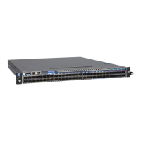
Model M4500-48XF8C
NETGEAR M4500 Series Switches Hardware Installation Guide 8
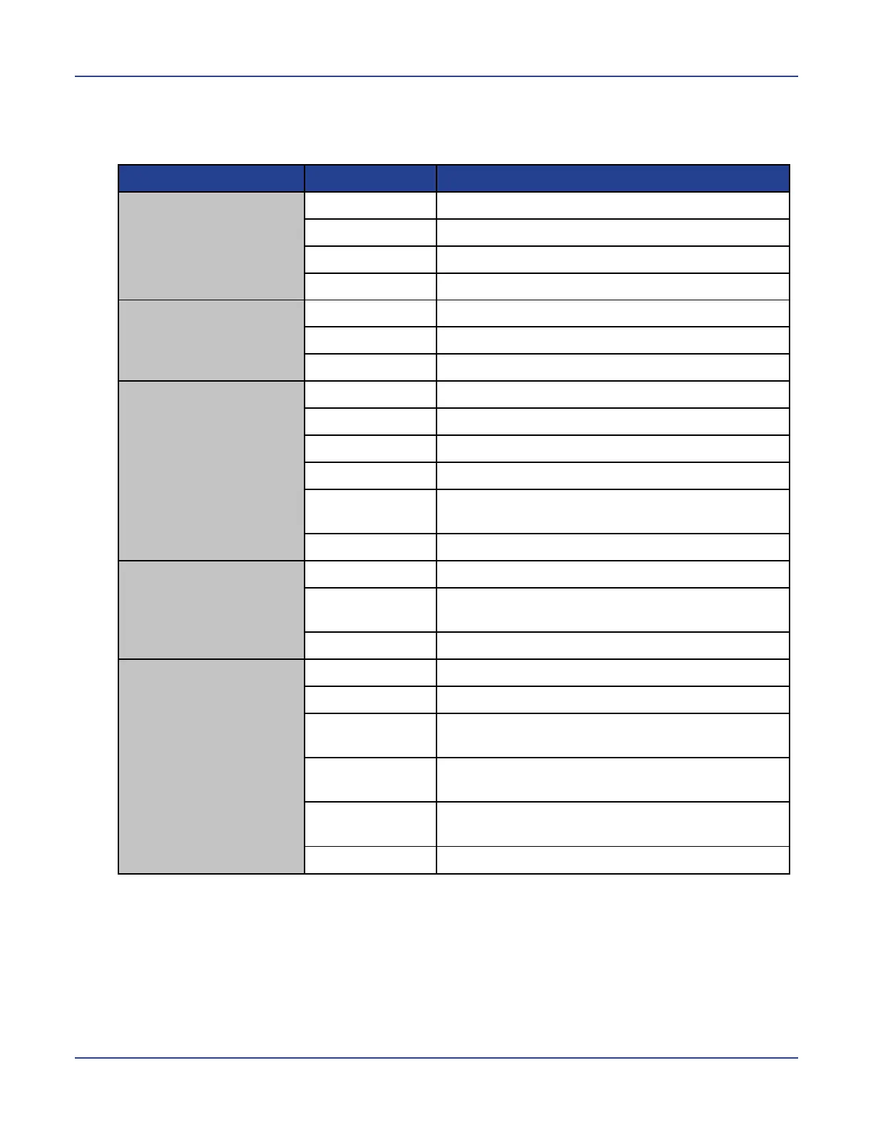
LED indicators of model M4500-48XF8C
System LEDs
PSU1 LED
PSU2 LED
(Power Supply Unit
LEDs, bicolor: green
and red)
One per switch on the front panel
The switch is nonoperational
One of the PSUs is operating abnormally
Both PSUs are operating normally
FAN LED
(bicolor: green and
red)
One per switch on the front panel
One of the fans is operating abnormally
All fans are operating normally
SYS LED
(System LED, bicolor:
green and amber)
One per switch on the front panel
The switch is nonoperational
An equipment even occurred
The switch has loaded the agent software code
and is operating normally
The switch is loading the agent software code
PWR LED
(Power LED, single
color: green)
One per switch on the front panel
The switch is nonoperational or a power failure
occurred
Power is provided to the switch
BMC LED
(Baseboard
Management
Controller LED,
bicolor: blue and
amber)
One per switch on the front panel
The switch is nonoperational
The BMC is operating normally
A “show switch location” occurred via the BMC
The switch has loaded the agent software code
and is operating normally
The switch is loading the agent software code
 Loading...