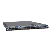
EasyManuals Logo

NETGEAR M4500 Series User Manual

NETGEAR M4500 Series
33 pages
To Next Page IconTo Next Page
To Previous Page IconTo Previous Page
Page #7 background imageLoading...
Page #7 background image
Model M4500-48XF8C
7 NETGEAR M4500 Series Switches Hardware Installation Guide
Rear view of the switch
No.
Item
No.
1
AC Power Connector (with Plug
Retainer)
6
2
Earth Grounding (M4 screw)
7
3
PSU Warning LED
8
4
PSU DC LED
9
5
PSU AC LED
On the rear panel, the left power supply is PSU2 and the right power supply is PSU1. The fan
modules from the left to the right are FAN6, FAN5, FAN4, FAN3, FAN2, and FAN1.

Other manuals for NETGEAR M4500 Series

Questions and Answers:

Question and Answer IconNeed help?

Do you have a question about the NETGEAR M4500 Series and is the answer not in the manual?

NETGEAR M4500 Series Specifications

General IconGeneral
BrandNETGEAR
ModelM4500 Series
CategorySwitch
LanguageEnglish

Related product manuals