Do you have a question about the NETGEAR M4250-10G2XF-PoE++ and is the answer not in the manual?
Details the NETGEAR AV Line M4250 Series switch models and their specifications.
Highlights the key hardware capabilities and configurations of the M4250 Series switches.
Provides essential safety guidelines for operating and handling the switch.
Describes the hardware features of the 8-port PoE+ and PoE++ switch models.
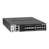
Details the hardware features of the 24-port PoE+ and PoE++ switch models.
Outlines the hardware features of the 40-port PoE+ and PoE++ switch models.
Explains the hardware features of the M4250-12M2XF LED tiles switch model.
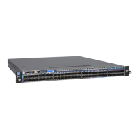
Details the hardware features of the M4250-16XF aggregation switch model.
Describes common hardware interfaces like RJ-45 and SFP+ ports on M4250 series.
Lists PoE port capacities, power budgets, and class allocations for M4250 switches.
Information on compatible SFP/SFP+ transceiver modules and cables for fiber connectivity.
Describes network cable types and their supported speeds for switch connections.
Explains the function and operation of the switch's dual-function reset button.
Details the function and requirements of the USB 2.0 port for firmware and configuration.
Describes the out-of-band Ethernet port for remote switch access.
Explains the RJ-45 RS-232 console port for direct console access.
Details the USB Type-C console port for direct console access.
Explains the intelligent fan operation modes and their behavior based on conditions.
Details fan operation thresholds and properties for 8-port models.
Details fan operation thresholds and properties for 24-port models.
Details fan operation thresholds and properties for 40-port models.
Details fan operation thresholds and properties for LED tiles and aggregation models.
Outlines the site requirements for installing the switch.
Provides essential precautions to prevent damage from electrostatic discharge (ESD).
Details the package contents and how to unpack the switch.
Guides on mounting the switch in a rack or placing it on a flat surface.
Explains how to install optional SFP/SFP+ modules into the switch's ports.
Instructions for connecting network devices to the switch's RJ-45 Ethernet ports.
Steps to verify the installation before applying power.
Procedure for connecting power and checking system LEDs.
Guide on connecting a console for switch configuration and management.
Lists common symptoms, causes, and solutions for switch problems.
Provides tips for diagnosing and resolving Power over Ethernet (PoE) issues.
Offers further suggestions for resolving persistent network or switch problems.
| Model | M4250-10G2XF-PoE++ |
|---|---|
| Category | Switch |
| Product Type | Managed Switch |
| Form Factor | Rack-Mountable |
| PoE Support | Yes |
| PoE Budget | 240W |
| MAC Address Table Size | 16K |
| Power Supply | Internal Power Supply |
| Humidity | 10% to 90% non-condensing |
| PoE Standard | IEEE 802.3af/at/bt (PoE++) |
| VLANs Supported | 4096 |
| Management | Web GUI, SNMP, CLI |
| Features | Layer 2, QoS, IGMP Snooping |
| Operating Temperature | 0°C to 50°C |