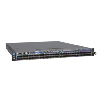
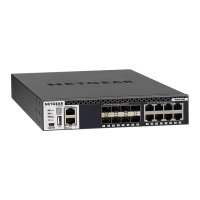
Note: Instead of using an RJ-45 Ethernet port, you can connect an SFP or SFP+ port
with an SFP or SFP+ transceiver module and cable to your network. For more
information, see Optional Step 5: Install SFP or SFP+ transceiver modules on page
53.
2. Connect devices to the RJ-45 Ethernet ports on the switch.
3.
Verify that all cables are installed correctly.
Step 7: Check the installation
Before you apply power to the switch, perform the steps that are described in this
section.
To check the installation:
1. Inspect the equipment thoroughly.
2.
Verify again that all cables are installed correctly.
3.
Check cable routing to make sure that cables are not damaged or creating a safety
hazard.
4. Make sure that all equipment is mounted properly and securely.
Step 8: Apply AC power and check the LEDs
The switch provides an On/Off power switch that controls the power.
Before connecting the power cable or cables, select an AC outlet that is not controlled
by a wall switch, which can turn off power to the switch.
In the following procedure, the steps that apply to a single power cable apply to each
power cable for the models that use two or three power cables.
To apply AC power:
1.
Connect the end of the power cable to the AC power receptacle on the back of the
switch.
2. Plug the AC power cable into a power source such as a wall socket or power strip.
3.
Turn the On/Off power switch in the On position.
4. Check to see that the LEDs light correctly.
Hardware Installation Guide55Installation
AV Line of Fully Managed Switches M4250 Series
 Loading...