Page 11 of 22
LED Descriptions
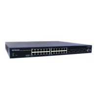
The front panel of the NETGEAR Model GSM7224 Managed Layer 2 Gigabit Ethernet Switch has LEDs
that provide a quick and accurate display of port speed, activity, and link state. The Gigabit Ethernet SFP
ports also have LEDs that show link and activity status. Table 2-1 summarizes the LEDs on the switch and
Gigabit Ethernet module.
Table 2-1. Front Panel LEDs
Label Color Activity Description
Power Green
Amber
On
On
Off
y Power supply present and operating normally
y Power supply present but failed
y Power supply is not present
Status
Green
Amber
On
On
y Green – Switch is operating normally
y Amber – Switch has failed to boot up
10/100/1000M bps Port
Speed (Left)
Link/Active (Right)
Green
Amber
Green
Green
On
On
Off
On
Blinking
Off
y Link in 1000Mbps
y Link in 100Mbps
y Link in 10Mbps
y Link up
y Activity, transmitting or receiving packet in link active
state
y No Link detected
SFP Port (1000M bps only) Green
Green
On
Blinking
Off
y Link up
y Activity, transmitting or receiving packet in link up
state
y No Link detected
Console Port
Your NETGEAR Model GSM7224 Managed Layer 2 Gigabit Ethernet Switch has a console port on the
front panel. This port is labeled Console and is required for initial management configuration of the
switch. It also lets you manage the switch using a directly connected VT-100 terminal, personal computer
(PC), Apple Macintosh, or UNIX workstation. The terminal, computer, or workstation connects to the
console port using the null-modem cable supplied with your switch.
The console port is configured to use the following settings:
• Baud rate: 9,600 bps
• Data bits: 8
• Parity: none
• Stop bit: 1
• Flow control: none
These settings appear below the connector on the switch front panel.
In addition to using the console port, you can manage the switch using a Web browser or a Simple Network
Management Protocol (SNMP) management program.
For more information about console-port connections, see Connecting to the Console Port to Manage the
Switch. For more information about managing the switch, see the User Guide located on the CD-ROM.
 Loading...