The T1/E1 ports are connected to the public network using 4-wire shielded 26 AWG or larger twisted pair telecommunication line cords with RJ-48
connectors.
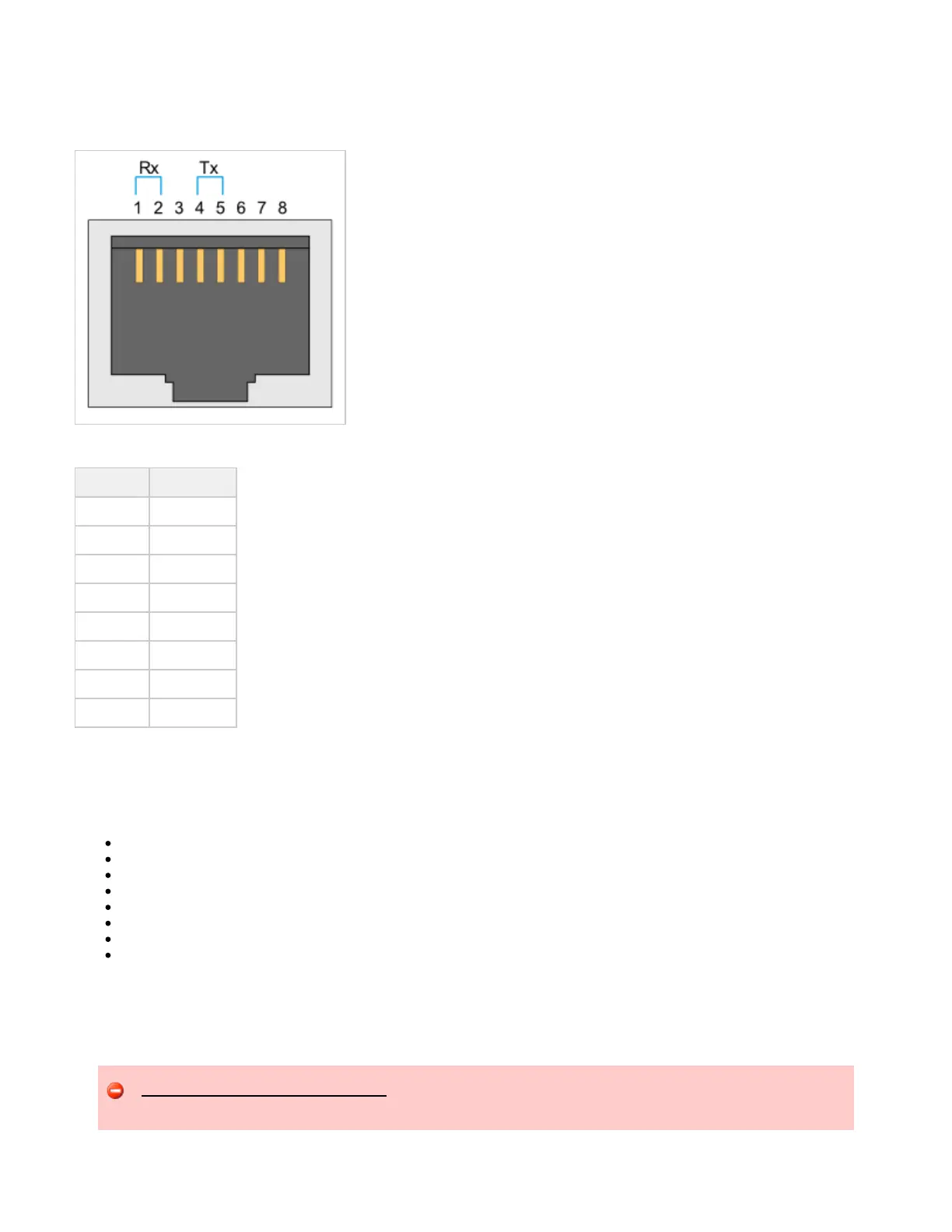
T1/E1 RJ-48 Connector
T1/E1 Connector Pinouts
Pin Number Description
1 Receive Ring
2 Receive Tip
3 no connection
4 Transmit Ring
5 Transmit Tip
6 no connection
7 no connection
8 no connection
Installing the UX2000 Hardware
This section describes how to prepare for and physically install a UX system.
Installation Warnings
Preparing for Installation
Installing the UX Chassis in a 4-Post Equipment Rack
Installing the UX Chassis in a 2-Post Equipment Rack
Installing Interface Cards
Installing Ground Wire, Power Cables and Connect Power
Installing the Cable Management Bracket
Next Steps
Installation Warnings
Review the , and before installing the UX chassis.Safety Requirements Precautions UX2000 Chassis Installation Requirements
Do not remove the top panel of the UX chassis. Operating the UX system with the top panel removed will cause hardware components
to overheat and fail. Unauthorized removal of the top panel will void your product warranty and service agreement.