9 DISMANTLING AND ASSEMBLY
OF THE PUMP HOUSING
PAGE
9.C
issued: 08.11.2010 Revision: 23.09.2010
text no.
09101-2/2
copy to: BR, EX, I, LOG, RC
I Slide the new stator (3000) into the stator housing (3001) with the inlet cone
positioned towards the input side of the pump and the faces at either end
protruding equally.
Tip:
Inspect the rotor when replacing the stator.
We recommend replacing the rotor (1999) as soon as clear signs of wear appear
Our Service Team would be pleased to answer any further questions you may have.
Step 6: Mount the iFD-Stator
®
(3005) on the pump
I Slide the iFD-Stator
®
(3005) onto the rotor (1999)
with the label facing upwards.
The iFD-Stator
®
appears to be slightly oversize when
it being assembled - allowing it to be easily slid onto
the rotor. This greatly simplifies stator replacement
and allows maintenance and downtimes to be
reduced to a minimum.
I Reinsert the thru bolts (3010) in the pump housing
(2010) and reassemble the end stub (2005).
I Tighten all nuts (3020).
Step 5: Assemble the iFD-Stator
®
(3005)
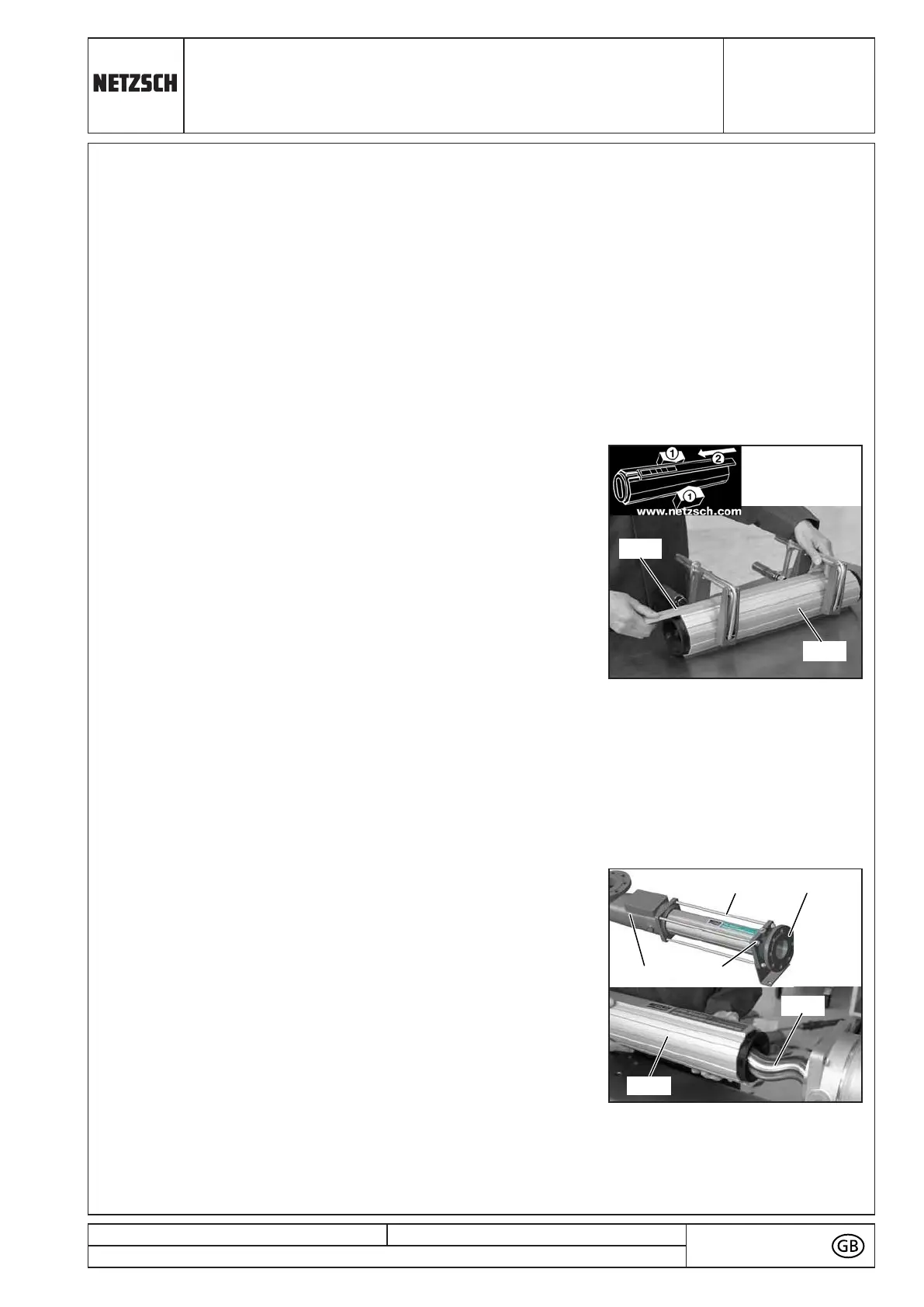
I To assemble the stator clamping sleeve (3002),
reclamp the stator housing (3001) across its diameter
and slightly compress the housing.
CAUTION!
Only compress the housing until the the clamping
sleeve can be easily slid onto the housing.
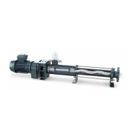
I Close the housing (3001) by sliding the clamping
sleeve (3002) over the housing guides - note that it
should not be necessary to use force to do this.
Tip:
It is recommended that the clamping sleeve, which is shorter than the housing, is slid
on until it is sitting centrally on the housing.
I Finally, release the housing from the clamps or vice.
CAUTION!
Check that the stator (3000) is centrally positioned in the stator housing (3001) before
releasing the clamps.
IPP - EN - EN_09101_20141105/3 - D8411276 - 4300003998 - 000100 - NPS - 00229929 N 2018-02-21 19:03:25